Must-have: VLANs are too important! Share examples of VLAN planning and configuration in two of the most common scenarios!
2025.03.07

1. Common Scenario 1 - Restaurant/Hotel
1. Background
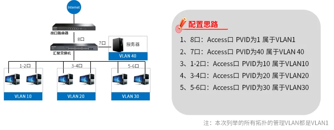
In general, small restaurants/hotels generally use the following topology when there are no more than 100 access terminals: all wired devices do not include wireless, and all terminal IP addresses are 192.168.0.0/16.
2. Network topology
3. ENSP experimental topology
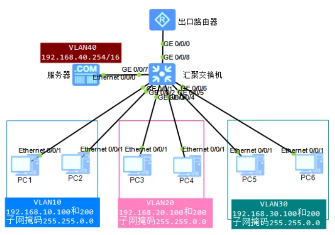
4. Configure commands
The server and PC1-PC6 can be configured according to the IP plan of the VLAN in the above figure, which is simple and omitted here.
The configuration of the VLAN aggregation switch is as follows:
<Huawei>system
[Huawei]vlan batch 10 20 30 40  //创建VLAN10 20 30 40
[Huawei]interface GigabitEthernet 0/0/1
[Huawei-GigabitEthernet0/0/1]port link-type access
[Huawei-GigabitEthernet0/0/1]port default  vlan 10
[Huawei-GigabitEthernet0/0/1]interface GigabitEthernet 0/0/2
[Huawei-GigabitEthernet0/0/2]port link-type access
[Huawei-GigabitEthernet0/0/2]port default  vlan 10
[Huawei-GigabitEthernet0/0/2]interface GigabitEthernet 0/0/3
[Huawei-GigabitEthernet0/0/3]port link-type access
[Huawei-GigabitEthernet0/0/3]port default  vlan 20
[Huawei-GigabitEthernet0/0/3]interface GigabitEthernet 0/0/4
[Huawei-GigabitEthernet0/0/4]port link-type access
[Huawei-GigabitEthernet0/0/4]port default  vlan 20
[Huawei-GigabitEthernet0/0/4]interface GigabitEthernet 0/0/5
[Huawei-GigabitEthernet0/0/5]port link-type access
[Huawei-GigabitEthernet0/0/5]port default  vlan 30
[Huawei-GigabitEthernet0/0/5]interface GigabitEthernet 0/0/6
[Huawei-GigabitEthernet0/0/6]port link-type access
[Huawei-GigabitEthernet0/0/6]port default  vlan 30
[Huawei-GigabitEthernet0/0/6]interface GigabitEthernet 0/0/5
[Huawei-GigabitEthernet0/0/5]port link-type access
[Huawei-GigabitEthernet0/0/5]port default  vlan 30
[Huawei-GigabitEthernet0/0/5]interface GigabitEthernet 0/0/7
[Huawei-GigabitEthernet0/0/7]port link-type access
[Huawei-GigabitEthernet0/0/7]port default  vlan 40
[Huawei-GigabitEthernet0/0/7]return
<Huawei>save //保存配置- 1.
- 2.
- 3.
- 4.
- 5.
- 6.
- 7.
- 8.
- 9.
- 10.
- 11.
- 12.
- 13.
- 14.
- 15.
- 16.
- 17.
- 18.
- 19.
- 20.
- 21.
- 22.
- 23.
- 24.
- 25.
- 26.
- 27.
- 28.
Run the dis port vlan command to view the VLAN configuration result:
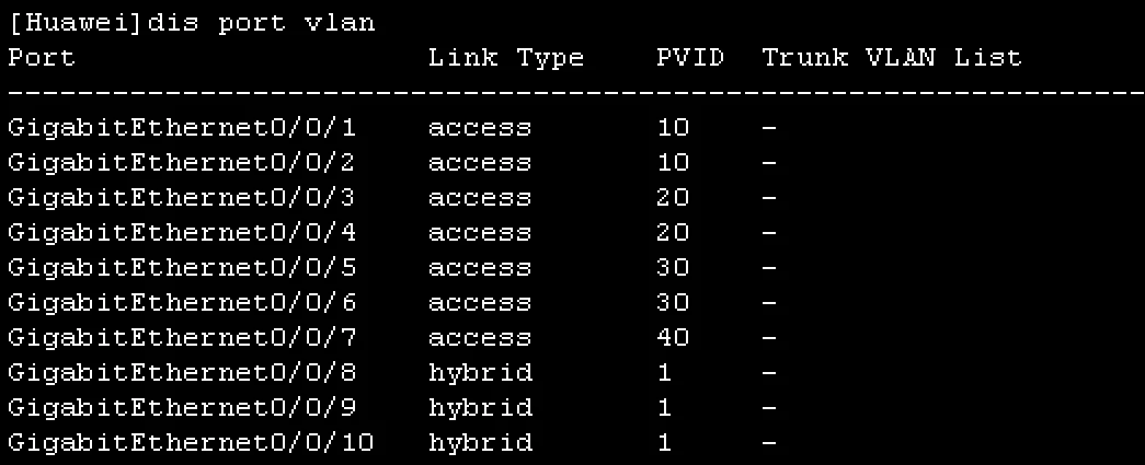
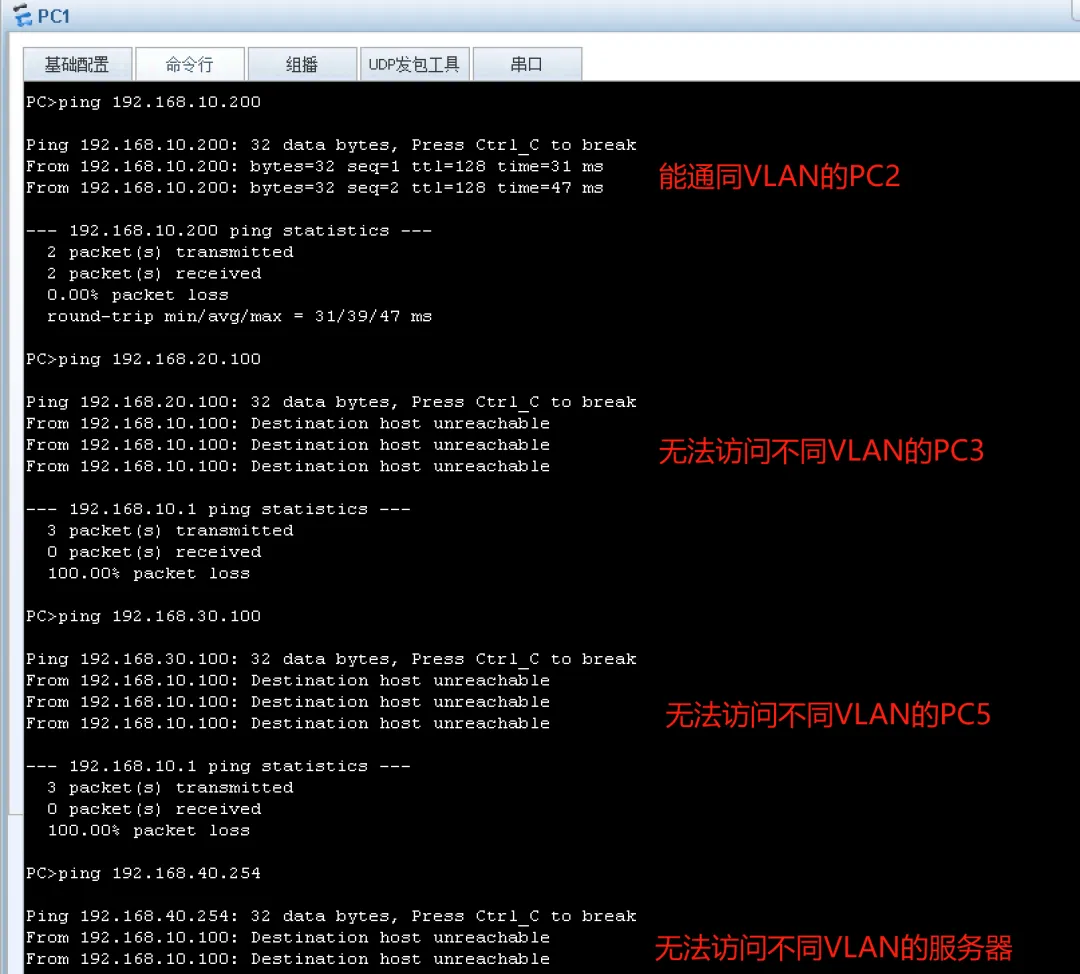
5. Experimental results
Test PC1 ping PC2, PC3, PC5 and server:
2. Common Scenario 2 - Office Space
1. Background
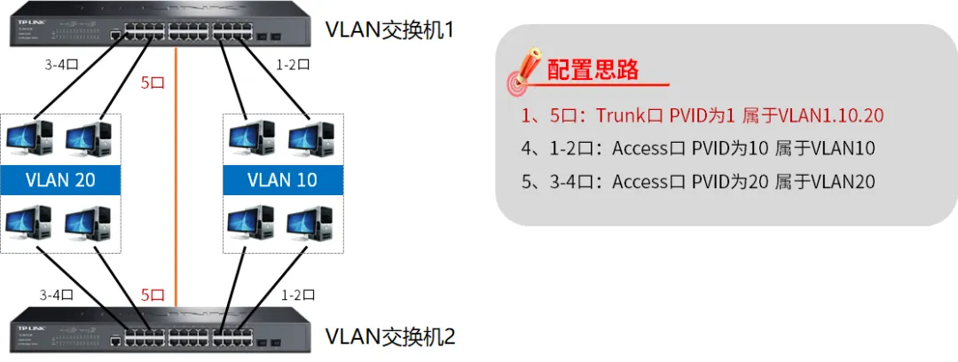
VLANs can be used to isolate VLANs that cannot communicate with each other in the same VLAN across devices. In some scenarios, the user office is distributed in two places, and all terminal CIDR blocks are 192.168.10.0/24, but two switches need to be connected to implement mutual access to the same VLAN and isolation of different VLANs.
2. Network topology
3. ENSP experimental topology

4. Configure commands
The server and PC1-PC6 can be configured according to the IP planning of the VLAN in the above figure, and the configuration is simple, omitted here.
In this example, VLAN switches 1 and 2 are configured the same as follows:
<Huawei>system
[Huawei]vlan batch 10 20  //创建VLAN 10和20
[Huawei]interface GigabitEthernet0/0/1
[Huawei-GigabitEthernet0/0/1] port link-type access
[Huawei-GigabitEthernet0/0/1] port default vlan 10
[Huawei-GigabitEthernet0/0/1]interface GigabitEthernet0/0/2
[Huawei-GigabitEthernet0/0/2] port link-type access
[Huawei-GigabitEthernet0/0/2] port default vlan 10
[Huawei-GigabitEthernet0/0/2]interface GigabitEthernet0/0/3
[Huawei-GigabitEthernet0/0/3] port link-type access
[Huawei-GigabitEthernet0/0/3] port default vlan 20
[Huawei-GigabitEthernet0/0/3]interface GigabitEthernet0/0/4
[Huawei-GigabitEthernet0/0/4] port link-type access
[Huawei-GigabitEthernet0/0/4] port default vlan 20
[Huawei-GigabitEthernet0/0/4]interface GigabitEthernet0/0/5
[Huawei-GigabitEthernet0/0/5]port link-type trunk   //端口类型为Trunk
[Huawei-GigabitEthernet0/0/5]port trunk allow-pass vlan 10 20  //透传VLAN10和20
[Huawei-GigabitEthernet0/0/5]return
<Huawei>save- 1.
- 2.
- 3.
- 4.
- 5.
- 6.
- 7.
- 8.
- 9.
- 10.
- 11.
- 12.
- 13.
- 14.
- 15.
- 16.
- 17.
- 18.
- 19.
Run the dis port vlan command to view the VLAN configuration result:
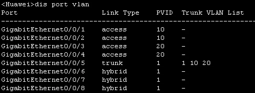
5. Experimental results
Test PC1 ping PC2, PC10, PC3 and PC30;

The following ping packets are transparently transmitted between the interconnected trunk ports of VLAN switches 1 and 2:
