RocketMQ implements AZ-level high availability based on Kosmos. Have you learned it?

1. Background
RocketMQ can ensure the high availability of RocketMQ clusters whether it adopts Master/Slave master-slave mode or Dledger's multi-copy mode. However, in some extreme scenarios, such as computer room power outage, computer room fire, earthquake and other irresistible factors, the The RocketMQ cluster in the IDC availability zone cannot normally provide external messaging service capabilities. Therefore, in order to enhance the anti-risk capability, multi-active remote disaster recovery of the message queue RocketMQ cluster is extremely important.
2. Physical deployment of remote disaster recovery plan
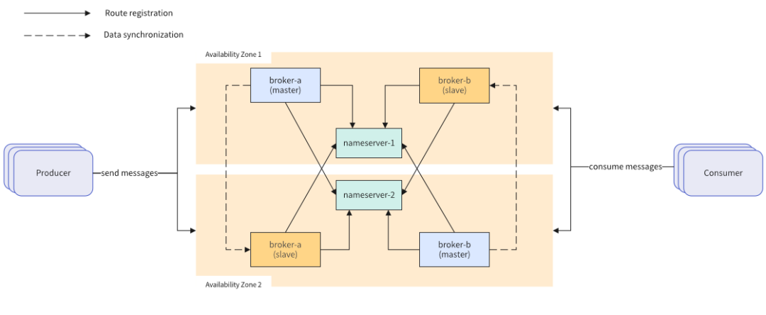 Figure 2-1 Physically deployed remote disaster recovery solution diagram
RocketMQ deployed in Mobile Cloud adopts the Master/Slave master-slave model. The physical deployment off-site disaster recovery solution includes the following parts:
(1) The NameServer component serves as a lightweight registration center and is stateless. It is responsible for updating and discovering the Broker service. There is no communication between Namesrv. The downtime of a single Namesrv does not affect the functions of other Namesrv nodes and the cluster. Two Namesrv are deployed in different places. Availability zone, when one availability zone fails, Namesrv in another availability zone can still provide external services.
(2) The Broker component acts as a message relay and is responsible for storing and forwarding messages. It adopts the Master/Slave deployment mode and is deployed cross-deployed in two availability zones (for example, the Master of broker-a is deployed in Availability Zone 1, and the Slave node is deployed in Availability Zone 1. In Availability Zone 2, the Master of broker-b is deployed in Availability Zone 2, and the Slave node is deployed in Availability Zone 1). After the message is sent to the Master node, it will be synchronized to the Slave node in real time, ensuring that each availability zone saves the full amount of messages. . When a single availability zone fails, external message reading and writing capabilities will also be provided.
3. Cloud version remote disaster recovery single cluster solution
Deployment of RocketMQ operation and maintenance, migration, expansion and contraction for physical machines is time-consuming and laborious, and the operation is complicated; after the business increases, resources cannot be elastic, and manual expansion and contraction are poor in real-time; the utilization rate of the underlying resources is not high, and user resource isolation and traffic control require additional investment and other issues. You can use K8S Operator. The working principle of Operator actually uses Kubernetes' custom API resources (such as using CRD, CustomResourceDefinition) to describe the application you want to deploy; then in the custom controller, according to the custom API object changes to complete specific deployment and operation and maintenance work. The main key to realizing Operator is the design of CRD (custom resource) and Controller (controller).
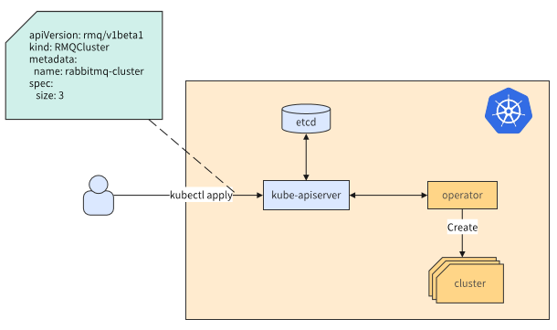 Figure 3-1 Operator schematic diagram
The self-developed RocketMQ Operator realizes a series of common operation and maintenance operations such as cluster deployment in seconds, expansion and contraction, and specification changes, thereby solving the problems caused by physical deployment. The following figure is the design and implementation of RocketMQ Operator:
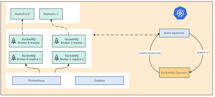 Figure 3-2 RocketMQ Operator architecture diagram
This solution uses three remote availability zones to deploy a K8S cluster, and each availability zone deploys a master node. The Broker in the figure is a two-master and two-slave high-availability solution, using cross-deployment, and namesrv deploys one instance in each availability zone.
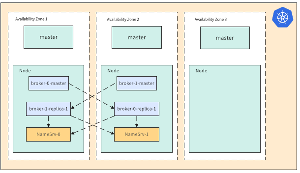 Figure 3-3 Cloud-based remote disaster recovery single cluster solution
There are several problems with this solution: when a large-scale single K8S cluster fails, it may have an impact on the entire cluster, and component upgrades are difficult and risky; as business increases, the pressure on core components increases and performance declines; the construction of a single cluster may Limited by specific geographical location and early planning, lack of flexibility.
4. Cloud version of remote disaster recovery cluster federation solution
In view of the shortcomings of the above solutions, the current optimization of the message queue RocketMQ cloud version with multiple availability zones is as follows:
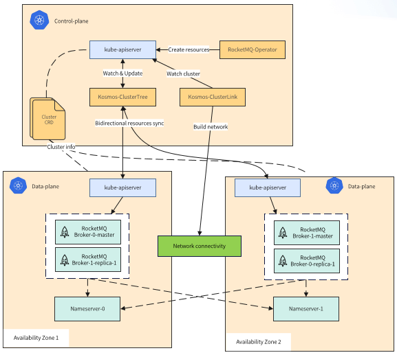 Figure 4-1 Cloud-based remote disaster recovery multi-federation cluster solution
K8S clusters use cloud-native Kosmos to federate multiple clusters. Instead of relying solely on a single K8S cluster, RocketMQ service resources synchronize svc, pod and other resources between federated clusters through Kosmos CluterTree. The network between federated clusters is opened by Kosmos ClusterLink.
5. Introduction to Kosmos
Kosmos is a collection of distributed cloud-native federated cluster technologies for mobile cloud. It will be open sourced in August 2023. The project address is: https://github.com/kosmos-io/kosmos. Kosmos includes multi-cluster network tool ClusterLink, cross-cluster orchestration tool ClusterTree, etc.:
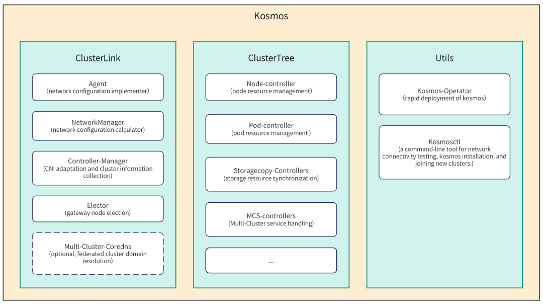 Figure 5-1 Kosmos modules and components
The function of ClusterLink is to open up the network between multiple Kubernetes clusters and is implemented on the upper layer of CNI. Users do not need to uninstall or restart the installed CNI plug-in, and it will not affect running pods. The main functions of ClusterLink are as follows:
✓ 提供跨集群PodIP、ServiceIP互访能力

  ✓ 提供P2P、Gateway多种网络模式

  ✓ 支持全局IP分配

✓ 支持IPv4、IPv6双栈- 1.
- 2.
- 3.
- 4.
- 5.
- 6.
- 7.
The role of ClusterTree is to implement tree expansion of Kubernetes and cross-cluster orchestration of applications. ClusterTree is essentially a set of controllers. Users can interact directly with the control plane kube-apiserver just like using a single cluster, without requiring additional code modifications. Currently, the main functions included in ClusterTree are as follows:
✓提供创建跨集群应用能力

  ✓兼容k8s api,用户零改造

  ✓支持有状态应用

✓支持k8s-native(需要访问kube-apiserver的)应用- 1.
- 2.
- 3.
- 4.
- 5.
- 6.
- 7.
In addition, Kosmos also provides some auxiliary tools. Among them, kosmos-operator simplifies Kosmos deployment. Kosmosctl is a command line tool that provides users with functions such as network connectivity testing, cluster management, and Kosmos deployment and installation.
6. Kosmos multi-cluster network ClusterLink
(1) ClusterLink workflow and principle
ClusterLink is based on Linux tunnel technology to open up cross-cluster networks. The tunnel type is configurable, such as VxLAN or IPSec. ClusterLink includes multiple components such as Network-Manager and Agent, as shown in the light blue part in the figure below. Each component cooperates with each other to complete network configurations such as tunnels, routing tables, fdb, etc.
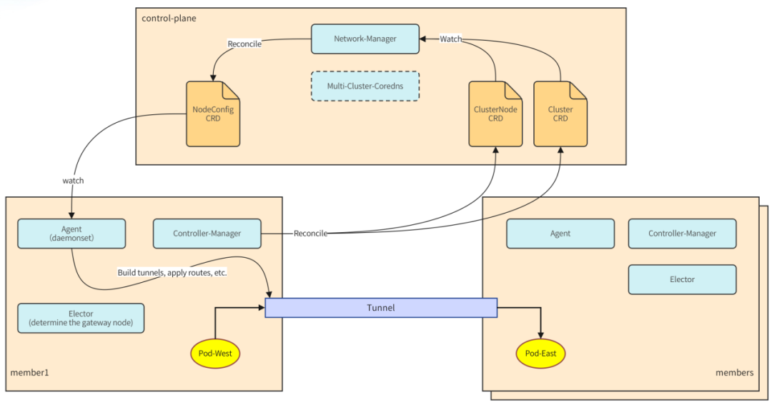 Figure 6-1 ClusterLink architecture
The workflow is as follows:
- First, the Controller-Manager component located in each sub-cluster is responsible for collecting cluster information, such as: podCIDR, serviceCIDR, node information, etc. This information will be saved in different locations under different CNI plug-ins, so the Controller-Manager contains some plug-ins to adapt CNI. The collected cluster information will be saved in two custom resources: Cluster and ClusterNode.
- Then, the Network-Manager component monitors the changes in these two CRs and calculates the network configuration required for each node in real time, such as network card information, routing table, iptables, arp, etc. The network configuration information of the corresponding node is stored in the NodeConfig custom resource object.
- Next, as the specific implementer of network configuration, agent, a daemonset, is responsible for reading the network configuration of the corresponding node and performing underlying network configuration. After the network configuration is completed, pods can be accessed across clusters through podIP and serviceIP.
(2) Introduction to ClusterLink network mode
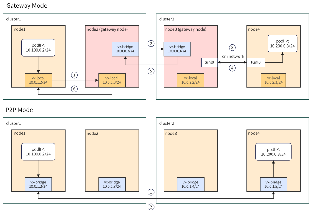 Figure 6-2 ClusterLink network mode
Currently, ClusterLink includes two network modes: Gateway and P2P. In Gateway mode, after the data packet is sent from the left pod, it first reaches the cluster gateway node through the intra-cluster tunnel vx-local. Then use the cross-cluster tunnel to reach the opposite cluster. After the data packet reaches the peer cluster, it is handed over to CNI for processing, and then travels through the single cluster network to reach the target pod. This model has advantages and disadvantages. The advantage is that each cluster only requires 1 node (2 when considering HA) to provide external access, and is suitable for cross-cloud hybrid cloud scenarios. The disadvantage is that because the network path is long, there is a certain performance loss. To address this problem, ClusterLink provides P2P mode, which can be used in scenarios with higher network performance requirements. In this mode, the control granularity of data packets is finer and will be sent directly to the node where the opposite pod is located. In addition, P2P and Gateway modes support mixed use.
7. Kosmos cross-cluster orchestration ClusterTree
(1) Introduction to ClusterTree components and principles
ClusterTree implements Kubernetes tree expansion and cross-cluster orchestration of applications. Users can access the root kube-apiserver just like using a single cluster. The Leaf cluster is added as a node in the root cluster. Users can use k8s native methods to control pod distribution, such as: labelSelector, affinity/anti-affinity, taint and tolerance, topology distribution constraints, etc.
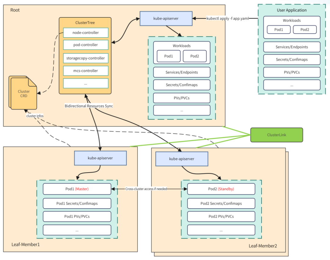 Figure 7-1 ClusterTree architecture
ClusterTree is essentially a set of controllers. The functions of each controller are as follows:
- node-controller: node resource calculation; node status maintenance; node lease update
- pod-controller: monitors root cluster pod creation, calls leaf cluster kube-apiserver to create pods; maintains pod status; environment variable conversion; permission injection
- storagecopy-controller: pv/pvc resource synchronization and status management
- mcs-controller: service resource synchronization and status management
(2) Introduction to ClusterTree high availability
When an AZ-level failure occurs, or the network between AZs is interrupted, it is very important to ensure that users can access RocketMQ cluster instances normally. As shown in the figure above, in order to cope with network disconnection or control plane failure at A, ClusterTree realizes the synchronization of service and endpoint resources, allowing user access traffic to go directly from the sub-cluster, decoupling management and business, and shortening the network path. RocketMQ's nameserver pod is distributed across clusters. When the network at B is disconnected or an AZ fails, users will have a 50% probability of accessing the failed nsv pod. To address this problem, ClusterTree's eps-probe plug-in will periodically detect cross-cluster eps and remove failed endpoints.
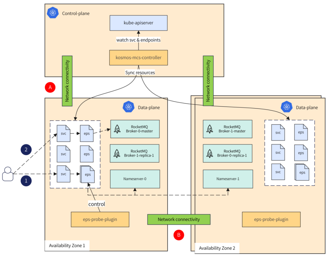 Figure 7-2 RocketMQ cross-AZ high availability
8. Kosmos cluster load and network performance testing
How many nodes and pods can ClusterTree manage? How does ClusterLink perform compared to a single cluster network? These are issues that users are very concerned about, and we have also conducted corresponding tests on this.
(1) Cluster load test
- The test standard
Kubernetes officially provides 3 SLIs (Service Level Indicator, Service Level Indicator) and the corresponding SLOs (Service Level Objective, Service Level Objective) value. SLIs include: read and write delays, stateless pod startup time (excluding image pull and init container startup), document address: https://github.com/kubernetes/community/blob/master/sig-scalability/slos/slos .md - test tools
- ClusterLoader2
ClusterLoader2 can test the SLIs/SLOs indicators defined by Kubernetes to verify whether the cluster meets various service quality standards. ClusterLoader2 will eventually output a Kubernetes cluster performance report, showing a series of performance indicator test results. https://github.com/kubernetes/perf-tests/tree/master/clusterloader2 - Kwok
is an open source project used to quickly simulate large-scale clusters. https://github.com/kubernetes-sigs/kwok
- Test Methods
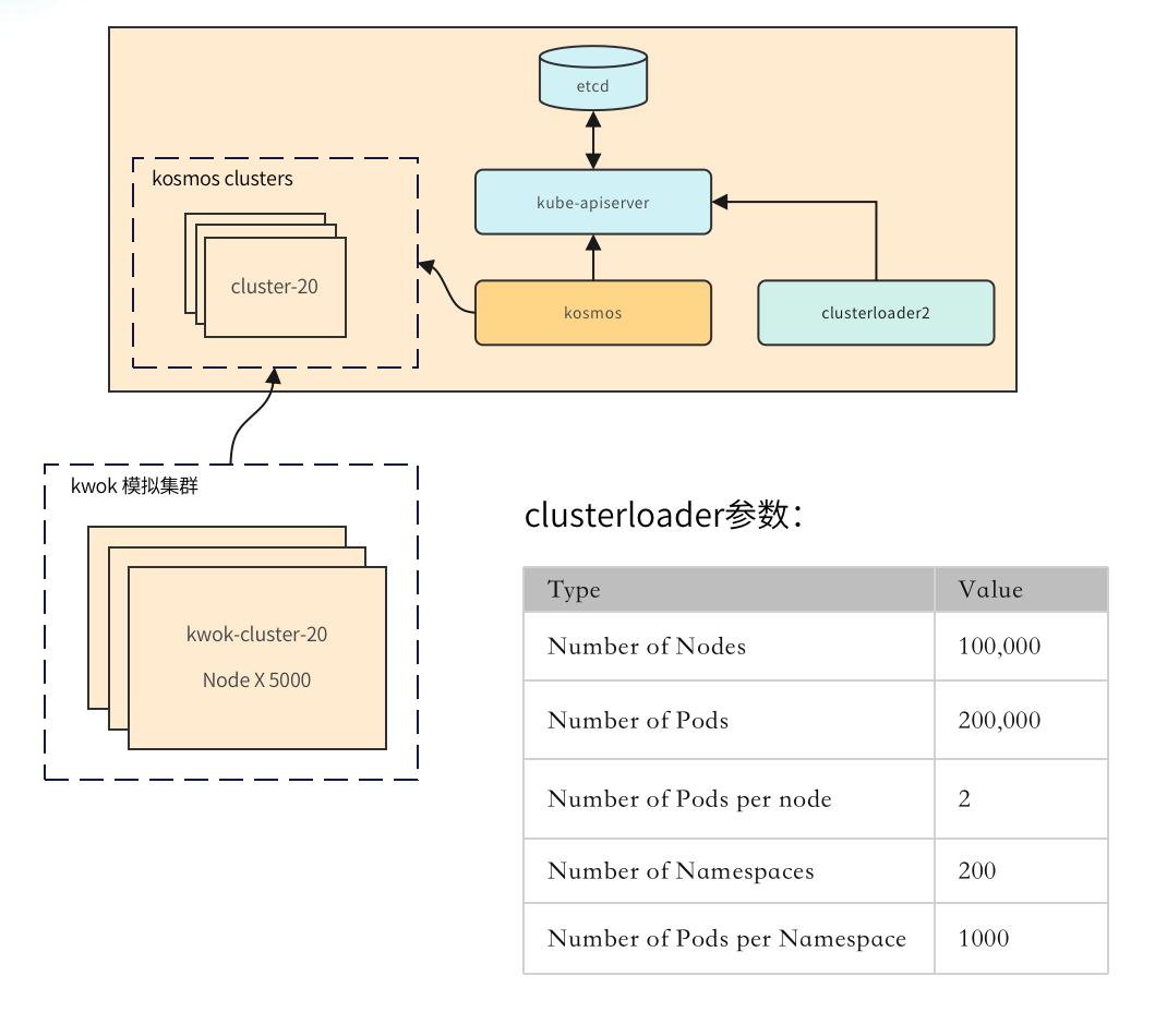 Figure 8-1 Cluster load test-test method
As shown in the figure, we first created 20 large-scale clusters through kwok, each cluster containing 5,000 nodes, and we used Kosmos to manage these clusters. Next, use clusterloader2 to connect to the control plane kube-apiserver for cluster load testing. The key test parameters are as shown in the figure.
- Test Results
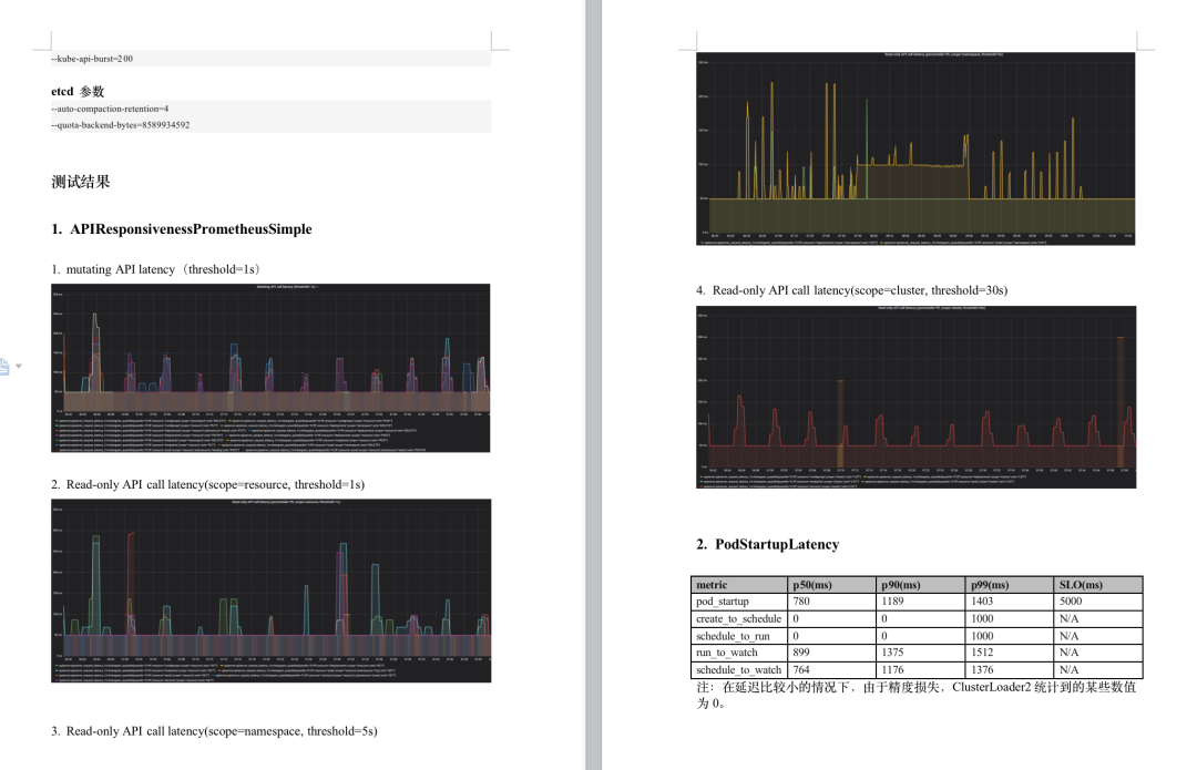 Figure 8-2 Cluster load test-test results
Using kosmos to manage k8s cluster federation, in the scenario of 100,000 nodes and 200,000 pods, it reaches the official SLOs standard, and the scale does not reach the upper limit of kosmos.
(2) Network performance test
- Test tool
iperf3 - Evaluation criteria
We use RTT (Round-Trip Time) delay to evaluate performance. RTT is round trip delay, which represents the total delay experienced by the sender from the time it sends data to the time the sender receives a confirmation from the receiver (the receiver sends a confirmation after receiving the data). - The test method
compares the RTT latency of a single-cluster network and a cross-cluster network, as shown in parts 1 and 2 below:
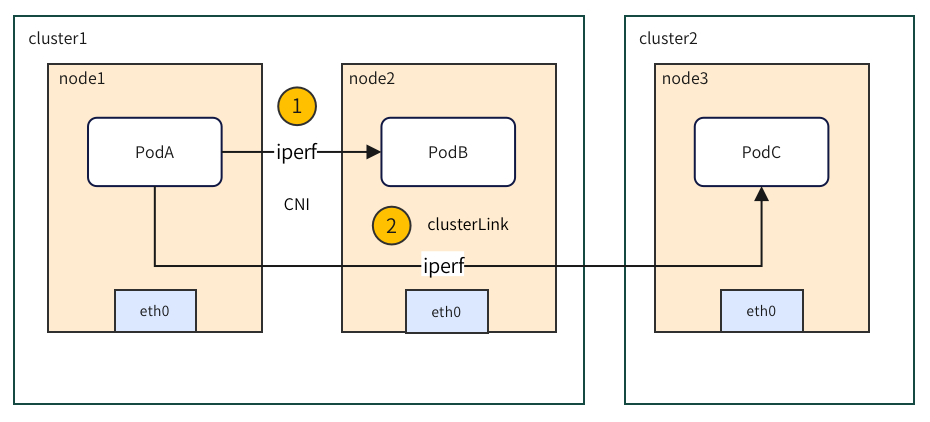 Figure 8-3 Network performance test-test method
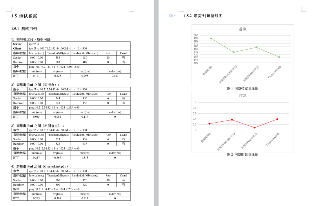
- The test results show
that across clusters, the RTT delay increases by about 6% compared to a single cluster.
 picture