A must-read for network novices: Detailed explanation of the three interface types of VLAN, allowing you to easily master them!
2023.10.27
A must-read for network novices: Detailed explanation of the three interface types of VLAN, allowing you to easily master them!
Depending on the interface type, the switch processes VLAN data frames differently. Next, let us understand how VLAN data frames are processed when passing through each interface.
What is VLAN?
VLAN (Virtual Local Area Network) is a communication technology that logically divides a physical LAN into multiple broadcast domains.
What is the difference between VLAN data frames and traditional Ethernet data frames?
IEEE 802.1Q is the official standard for VLAN. It adds a 4-byte 802.1Q Tag to the traditional Ethernet data frame (between the source MAC address field and the protocol type field).
Among them, the VID (VLAN ID) field in the data frame is used to indicate the VLAN to which the data frame belongs, and the data frame can only be transmitted within the VLAN to which it belongs.
What are the functions of VLAN?
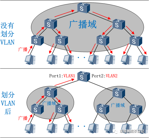
As can be seen from the above figure, by dividing different VLANs, hosts within the VLAN can communicate directly with each other, but VLANs cannot directly communicate with each other, thus limiting broadcast messages to one VLAN. Here the editor summarizes the advantages of VLAN technology, let’s take a look:
- Restrict broadcast domain: The broadcast domain is restricted to a VLAN, which saves bandwidth and improves network processing capabilities.
- Enhance the security of the LAN: Packets in different VLANs are isolated from each other during transmission, that is, users in one VLAN cannot communicate directly with users in other VLANs.
- Improve the robustness of the network: faults are limited to one VLAN, and faults in this VLAN will not affect the normal operation of other VLANs.
- Flexible construction of virtual workgroups: VLAN can be used to divide different users into different workgroups. Users in the same workgroup do not have to be limited to a fixed physical range, making network construction and maintenance more convenient and flexible.
How are VLAN data frames processed when passing through each interface?
What types of interfaces are there on the device? Follow the editor and take a look!
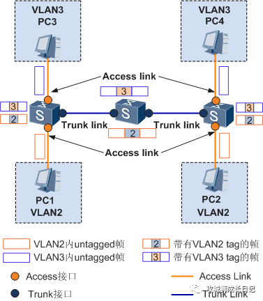
- Access interface: The interface on the switch used to connect to user hosts. It can only connect to access links (Access Link).
- Trunk interface: The interface on the switch used to connect to other switches. It can only connect to trunk links (Trunk Link).
In addition, there is another interface called the Hybrid interface, which is an interface on the switch that can connect to both the user host and other switches. Hybrid interfaces can connect to both access links and trunk links.
Hybrid interfaces and Trunk interfaces have the same processing methods when receiving data. The only difference is that when sending data, the Hybrid interface allows packets from multiple VLANs to be sent without tags, while the Trunk interface only allows packets from the default VLAN to be sent without tags.
Depending on the interface type, the switch processes VLAN data frames differently. The specific processing methods are as follows:
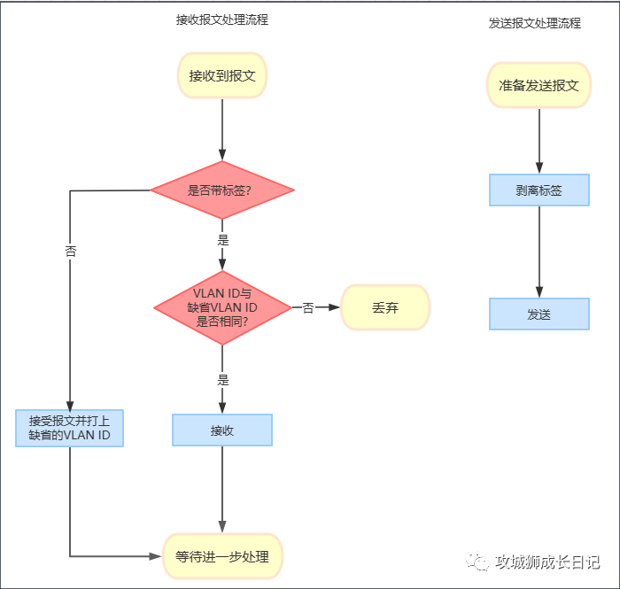
Access interface sending and receiving data packet processing flow
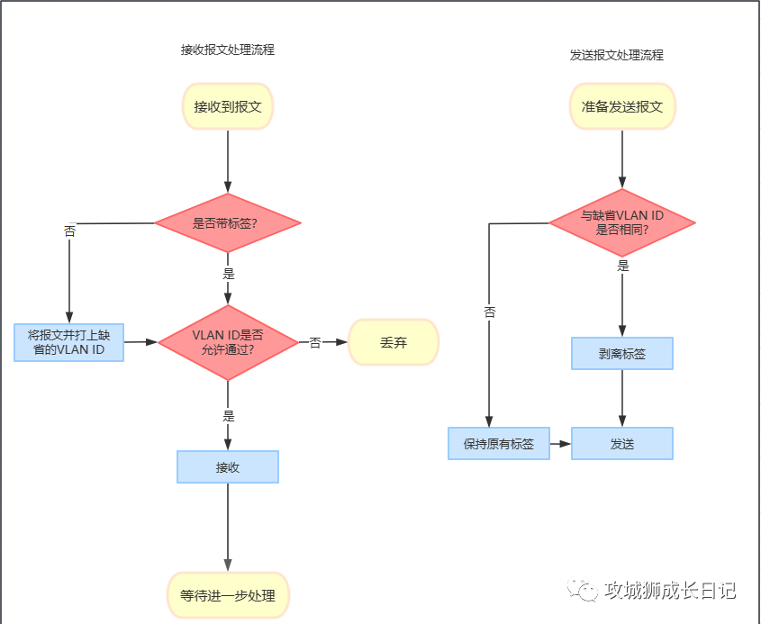
Trunk interface sending and receiving data packet processing flow
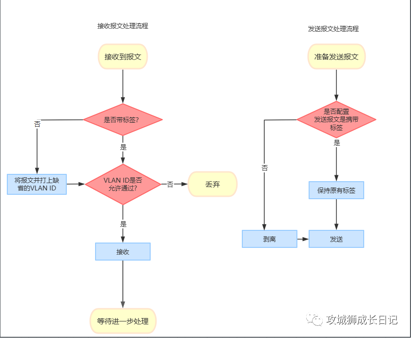
Hybrid interface sending and receiving data packet process
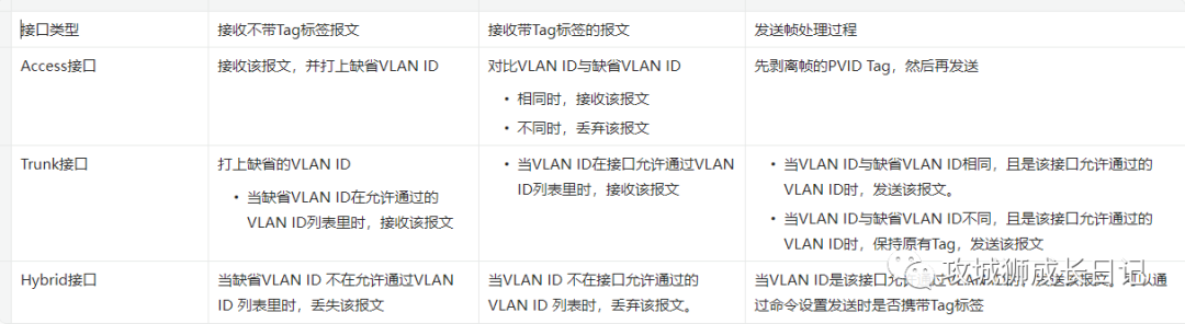
3 types of summary:
Case presentation
1.Basic configuration
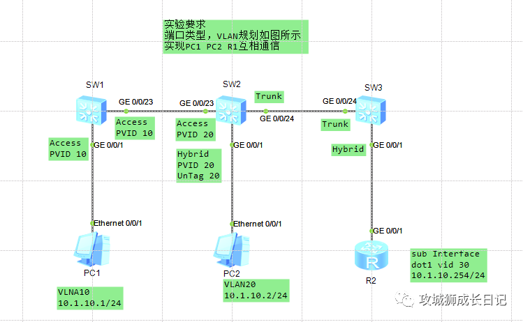
Complete the basic configuration according to the plan in the picture above:
vlan batch 10


interface GigabitEthernet0/0/1
 port link-type access
 port default vlan 10

interface GigabitEthernet0/0/23
port link-type access- 1.
- 2.
- 3.
- 4.
- 5.
- 6.
- 7.
- 8.
- 9.
vlan batch 20

interface GigabitEthernet0/0/1
port hybrid pvid vlan 20

interface GigabitEthernet0/0/23
 port link-type access
#
interface GigabitEthernet0/0/24
port link-type trunk- 1.
- 2.
- 3.
- 4.
- 5.
- 6.
- 7.
- 8.
- 9.
- 10.
vlan batch 30
interface GigabitEthernet0/0/24
port link-type trunk- 1.
- 2.
- 3.
interface GigabitEthernet0/0/1.30
 dot1q termination vid 30
 ip address 10.1.10.254 255.255.255.0
arp broadcast enable- 1.
- 2.
- 3.
- 4.
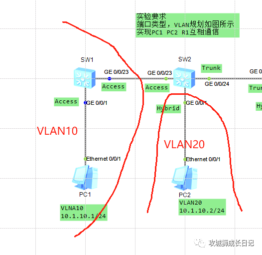
2. Realize mutual access between PC1 and PC2
According to VLAN communication rules, the same VLAN can communicate together. Therefore, GE0/0/23 of SW1 is also labeled with VLNA10:
interface GigabitEthernet0/0/23
 port link-type access
port default vlan 10- 1.
- 2.
- 3.
At this time, they cannot communicate because one side is VLAN 10 and the other side is VLAN 20. The key is whether to configure VLAN 10 or VLAN 20 on GE0/0/23 of SW2? Smart friends, you already know that you need to add VLAN20. The reason is very simple. The same VLAN can communicate with each other. GE0/0/1 of SW2 is configured with a default VLAN ID of 20.
interface GigabitEthernet0/0/23
 port link-type access
 port default vlan 20

interface GigabitEthernet0/0/1
 port hybrid pvid vlan 20
port hybrid untagged vlan 20- 1.
- 2.
- 3.
- 4.
- 5.
- 6.
- 7.
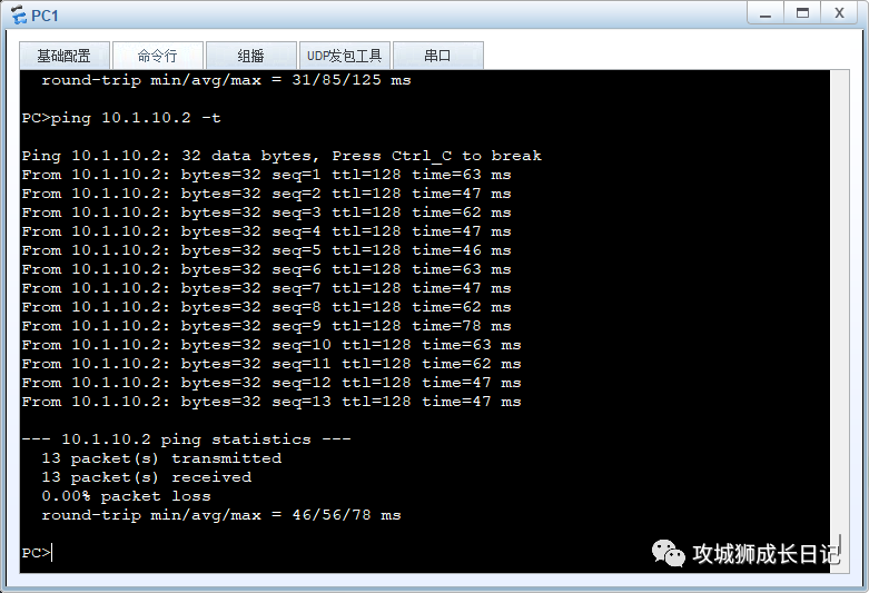
Validation results:
3. Implement communication between PC1 and router R1
When the PC1 data packet arrives at GE0/0/24 of SW2, it carries the label of VLAN20, and the default PVID of Truk is 1. When the data packet reaches the router, the two VLAN IDs are different, so communication cannot occur. Implementation ideas:
- When the packet comes to the GE0/0/24 interface of SW2, it strips the 20 label and runs 20 through
- When the data packet comes to the GE0/0/1 interface of SW3, it is labeled with 30 and runs 30 to pass
The key code is as follows:
# SW2
interface GigabitEthernet0/0/24
 port link-type trunk
 port trunk pvid vlan 20
 port trunk allow-pass vlan 20

# SW3
interface GigabitEthernet0/0/24
 port link-type trunk
 port trunk pvid vlan 30
 port trunk allow-pass vlan 30

interface GigabitEthernet0/0/1
 port hybrid pvid vlan 30
port hybrid tagged vlan 30- 1.
- 2.
- 3.
- 4.
- 5.
- 6.
- 7.
- 8.
- 9.
- 10.
- 11.
- 12.
- 13.
- 14.
- 15.
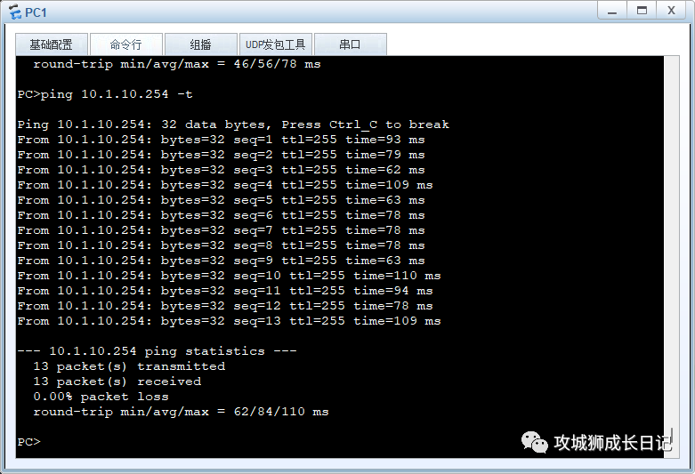
Validation results:
The topology address storage address is https://gitee.com/didiplus/datacom.git. If you want to learn math, you can pay attention to this project. All topology projects in the future will be stored here. Interested friends are also welcome to maintain it together. In order not to forget every issue, you can click watch to follow this project:
