In order to solve network congestion, what black technologies does Wi-Fi 6 use?
2022.05.14

In order to solve network congestion, what black technologies does Wi-Fi 6 use?
The real popularity of Wi-Fi started with Wi-Fi 4 (802.11n) in 2008. Arguably, since then, Wi-Fi has truly become the most common way to get internet access in homes and businesses. The number of device models that support Wi-Fi has also risen exponentially.
In the last article ( link ), I introduced you to the principle of Wi-Fi channel competition access. The core of Wi-Fi device access is carrier sense multiple access/collision avoidance (CSMA/CA).
This listen-before-talk mechanism has been in use since the first generation of Wi-Fi (802.11) in 1997. However, there were very few wireless network devices more than 20 years ago, and no one would consider the problem of network congestion caused by competition for access to the network when the number of devices increased.
The real popularity of Wi-Fi started with Wi-Fi 4 (802.11n) in 2008. Arguably, since then, Wi-Fi has truly become the most common way to get internet access in homes and businesses. The number of device models that support Wi-Fi has also risen exponentially.
Today, Wi-Fi devices are ubiquitous in our lives. Just open the wireless routing management interface at home, there may be no less than 10 Wi-Fi devices online at the same time.
The increase in the number of devices has led to problems such as network congestion, performance degradation, and increased latency. These problems are exacerbated in the era of Wi-Fi 5 (802.11 ac). So, when designing Wi-Fi 6 (802.11ax), experts made improvements and innovations specifically for network congestion.
So, what new technologies does Wi-Fi 6 use to improve wireless channel capacity?
Orthogonal Frequency Division Multiple Access OFDMA
Friends who are familiar with Wi-Fi should know that the air interface of Wi-Fi adopts the modulation method of Orthogonal Frequency Division Multiplexing (OFDM), that is, the entire bandwidth is composed of mutually orthogonal sub-carriers.
In Wi-Fi 6, the 802.11 working group introduced OFDMA access from LTE. The addition of such an "A" character can be said to have brought a qualitative change to the network capacity.
As shown in the figure on the left below, Wi-Fi 5-based OFDM can only allocate all bandwidth in the channel to one user at any time period, even if the user's data requirements do not need to occupy all the bandwidth.
When other users access the network, they need to wait for the next transmission opportunity window (TXOP). This is very inefficient in the use of channel resources, especially when the number of devices increases significantly.
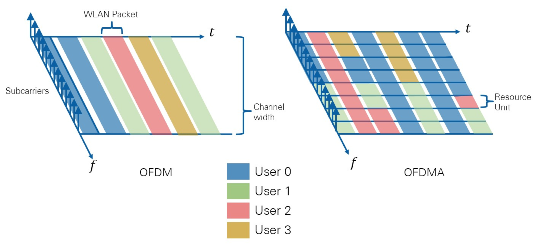
Figure 1 Comparison of OFDM and OFDMA
OFDMA changes that. OFDMA can dynamically divide the instantaneous bandwidth to different users by forming subcarriers into resource units (RUs).
For example, in the picture on the right of the above figure, the first TXOP is allocated to user 0 and user 1, the second OP is all allocated to user 2, and then in the third TXOP, the resources are evenly allocated to four users.
OFDMA suddenly increases the number of users that can be supported instantaneously.
Take the 20MHz bandwidth in the following figure as an example. After subcarrier allocation, 20MHz can support up to 9 devices accessing simultaneously, 40MHz can support 18 devices, and so on.
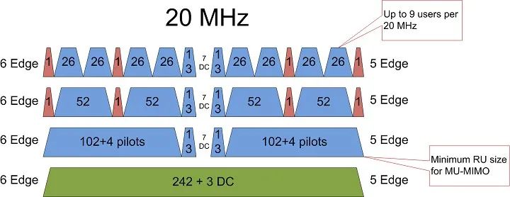
Figure 2 Number of resource elements available at 20MHz with OFDMA
(Each subcarrier in Wi-Fi 6 is 78.125khz, and 20MHz is 256 subcarriers. 6 Edge means that there are 6 subcarriers away from the edge as a guard band.)
It can be said that OFDMA has brought qualitative changes to the capacity of Wi-Fi channels.
BSS coloring
In the past Wi-Fi technology, inter-cell co-channel interference (Co-Channel Interference, CCI) is another important factor affecting channel capacity.
As mentioned in the previous article, the core of CSMA/CA is to use listen before talk (LBT). The device first monitors the wireless channel and sends data when it is not occupied.
In the case of multi-AP mesh networking (AP, Access Point, wireless access point), the devices in the cell will listen to the interference signal of the cell adjacent to the same channel, which will cause the device to mistakenly believe that the wireless channel of the cell is currently active. is occupied, so stop sending.
This interference, when the network is not optimized or the number of available channels is low, can significantly reduce network capacity.
As shown in the figure below, four Wi-Fi APs use three-channel networking. However, since there are only three available channels, AP1 and AP2 have to be deployed on the same channel Channel 6. At this time, the signal of AP2 is interference to the user equipment belonging to AP1 - Overlapped Basic Service Set (OBSS, Overlapping basic service units can be understood as overlapping cells with the same frequency).
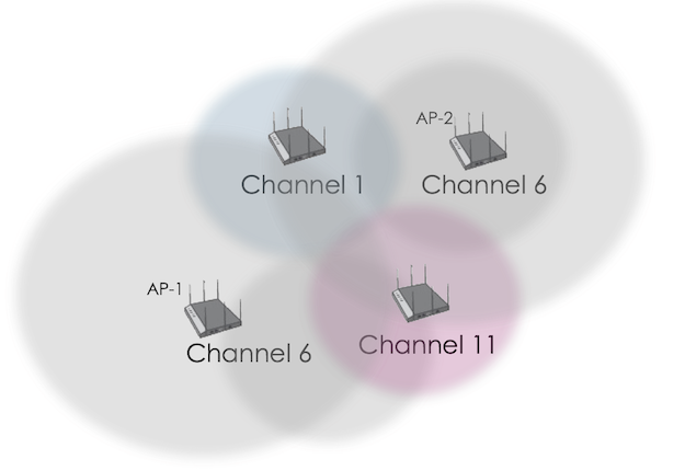
Figure 3 Co-channel interference scenario in tri-band network
When the user equipment communicates with AP1, since the device receives the interference signal of AP2 on the same frequency, the user equipment will mistakenly believe that the cell of AP1 is being occupied by other devices in the cell at this time, so it waits for the next time period to send. As a result, network performance is degraded.
Not only multi-cell networking, this interference problem also occurs when Wi-Fi APs are very close. For example, although there is only one wireless AP in your home, if the neighbor next door also has an AP deployed on the same channel as you, CCI will also lead to a decrease in the success rate of your device access.
Sadly, most manufacturers ship their devices with the Wi-Fi AP's default channel on the first channel. In this case, the interference problem is even more serious. If you find this kind of problem, you may wish to change the channel of the Wi-Fi AP in your home, which will significantly reduce interference and increase the network speed.
The solution of Wi-Fi 6 is to distinguish the local cell from the interfering cell by introducing the BSS Coloring (cell color coding) technology in the MAC layer. That is to say, when working on the same channel, there are APs that interfere with each other, and different color codes will be attached to distinguish them.
When the user equipment receives the AP signal, it will compare whether the color it receives is consistent with the color of the currently associated AP. Only when the colors are the same, the user considers the signal to be the signal in the cell.
If the color of the received signal is different from the color of the associated AP, the user determines that the signal is an interfering signal. As shown in the figure below, due to the use of different color codes, the channel 1 of the green cell is no longer interfered by the adjacent cell channel 1 (blue and red).
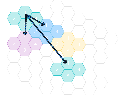
Figure 4 BSS Coloring Technology in Wi-Fi 6
When you see this, you may ask, even if the color is marked, the interference signal will still be received, how to solve the interference?
In the last article, we said that in Wi-Fi, there are two detection thresholds, which are to detect signal power (SD) and channel energy (ED) respectively. These two thresholds are fixed in the previous Wi-Fi technical standards and equipment, and cannot effectively distinguish between the signal of the current cell and the signal of the neighboring cell (the left side of the figure below).
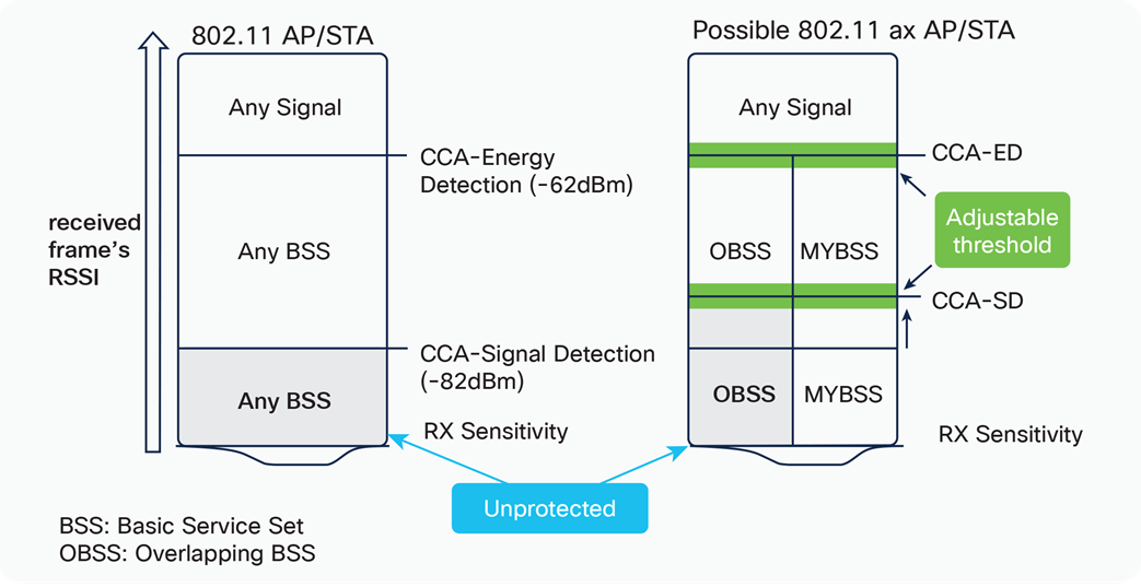
Figure 5 Differential signal detection threshold and dynamic adjustment
Wi-Fi 6 adopts differentiated detection thresholds, and assigns different detection thresholds to cells with different color codes (right side of the above figure).
The specific method is to raise the signal detection threshold of the interfering cell using the same frequency channel, and at the same time lower the signal detection threshold of the same color in this cell. Usually, the signal strength of the interference signal in the surrounding cells will be low due to propagation attenuation, and will not exceed the detection threshold of relatively high amplitude. The lower detection of the signal in the cell helps to improve the detection sensitivity.
Through this differentiated threshold detection, the channel will not be misjudged as being occupied, thereby improving the channel capacity.
At the same time, the signal detection threshold can be dynamically adjusted with the network environment, which can be said to be an implementation form of a self-aware network.
Multi-User Coordination, Multiple Input Multiple Output (MU-MIMO)
Single-User Multiple-Input-Output (SU-MIMO), introduced from Wi-Fi 5. APs and terminals use multiple antennas to transmit and receive, and multiple antennas use signals of the same frequency but orthogonal to each other to improve channel utilization.
Phones typically use two Wi-Fi antennas and support 2x2 MIMO—two transmit and receive.
Since the AP is not limited by size and power, it can do 4 or even 8 antennas. MU in MU-MIMO refers to multiple users. An AP uses the same channel to serve multiple different users. Each user is allocated 1-2 antennas. The signals between each antenna are orthogonal and mutually exclusive. interference.
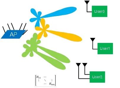
Figure 6 AP uses MU-MIMO to multiplex channels
Although Wi-Fi 5 added downlink MU-MIMO in the standard update of wave 2, most manufacturers did not implement MU-MIMO on the device.
In the era of Wi-Fi 6, MU-MIMO has finally been applied and extended to the uplink, that is, multiple terminal devices can not only receive at the same time, but also send data to the AP at the same time using the same channel.
With MU-MIMO and OFDMA, it is natural to think that if the AP can coordinate the multiple users it serves to access the channel at the same time, instead of competing for requests one by one, the channel utilization rate will increase.
As shown in the figure below, the AP sends a trigger signal to synchronize the start and end times of the 4 users that need to be connected. The four users no longer compete for channel resources with each other, but use MU-MIMO or OFDMA to communicate with the AP.
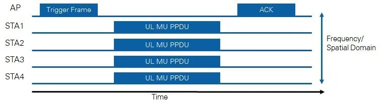
Figure 7 Multi-channel transceiver coordination function of Wi-Fi 6
Epilogue
Wi-Fi 6 is the most important update in Wi-Fi history.
Even the latest Wi-Fi 7 is only a few enhancements to the main features of Wi-Fi 6.
There are many more updates to Wi-Fi 6, such as 1024QAM modulation, Target Wake Time, etc. Today we only introduce features related to network capacity.
The increase in network capacity is the most useful feature in my opinion among the many updates of Wi-Fi 6, and it is also an important reason for enterprise and individual users to upgrade Wi-Fi networks and terminals.
In order to increase system capacity, Wi-Fi engineers have tried every means of physical layer and MAC layer. However, the final capacity is still limited by the Shannon limit.
To further fundamentally increase network capacity, it can only be solved from the perspective of increasing spectrum. In particular, the existing 2.4GHz has become crowded due to the use of a large number of wireless devices such as Bluetooth and remote controls. And 5GHz, there are many access restrictions.
Spectrum resources become very limited for Wi-Fi systems. This promoted the birth of Wi-Fi 6E.
Wi-Fi 6E expands the existing Wi-Fi 6 to 6GHz (5925-7125 MHz), which triples the capacity of the spectrum at once. At the same time, 6GHz is also the preliminary foreshadowing of 802.11 organizations for Wi-Fi 7 (IEEE802.11 be).
So, how do Wi-Fi 6E and Wi-Fi 7 improve performance? I will tell you one by one in the next article.
The author of this article, Dr. Xin Tang, is currently the technical director of Spectrum Lab.
references
[1] Aruba Networks White Paper – 802.11ax.
[2] Cisco White Paper- IEEE 802.11ax: The Sixth Generation of Wi-Fi.
[3] National Instruments - Introduction to 802.11ax High-Efficiency Wireless