Five-minute technology talk | One article to understand how to send and receive information between computers

Five-minute technology talk | One article to understand how to send and receive information between computers

Part 01 Physical Layer
If a computer wants to transmit information with another computer in the network, the first thing to do is to connect the computers, that is, to connect this computer with other computers through media such as optical fibers, cables, twisted pairs, etc. connected so that information can be transmitted. Therefore, the function of the physical layer is actually to connect two computers, and then transmit electrical signals in the form of 0 and 1 between the computers with high and low electrical frequencies.
Part 02 Data Link Layer
However, if the 0 and 1 signals between computers do not have a unified and recognized rule, the computer cannot interpret them. Therefore, the Ethernet protocol appeared.
 picture
Figure 1 Bitstream
2.1 Ethernet protocol
In the Ethernet protocol, a data packet composed of a group of electrical signals is called a frame. In addition, the frame contains its header and data, its size is generally 64-1518 bytes, and the header part is fixed at 18 bytes. Therefore, if the data to be transmitted is large, it is divided into multiple frames for transmission. The header of the frame generally stores some descriptive data, such as the sender, receiver, etc., and the data part stores the specific content to be sent to the receiver.
2.2 MAC address
 picture
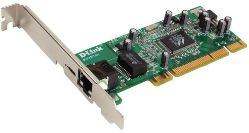
Figure 2 network card
In the process of sending the data in one computer to another computer through the physical layer and link layer, in order to distinguish different computers, a unique identifier of each computer - MAC address is generated. Among them, each computer connected to the network will have its own network card, and each network card will have its own unique address, that is, a MAC address.
2.3 broadcast
In a network, computer A is not only connected to computer B, but also to other computers. Suppose computer A knows the MAC address of computer B and wants to send information to computer B, but computer A does not know which route computer B is on. Thus, broadcasting appeared.
In the same subnet, computer A sends information to computer B, because the data packet contains the MAC address of computer B (assuming that computer A already knows the MAC address of computer B, the reason will be explained in the ARP protocol in the next section ). When sending information, computer A sends it by broadcasting. At this time, after receiving the data packet, computer C or D in the same subnet will take out the MAC address in the data packet and compare it. If the MAC addresses are the same, the data packet is received, otherwise the data packet is discarded.
Part 03 Network Layer
 picture
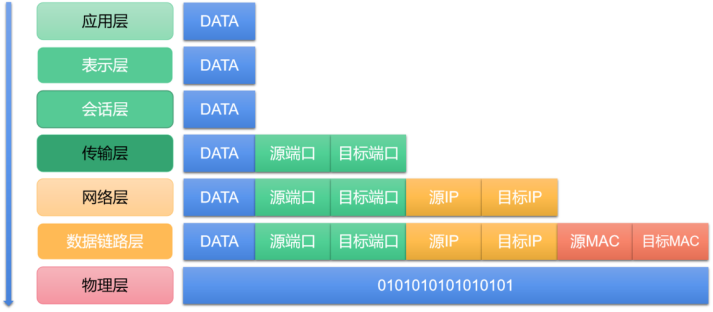
Figure 3 OSI reference model
The subnet mentioned in the previous section, in fact, the network we are in is composed of countless subnets, and only computers in the same subnet can receive it when broadcasting.
If there is no subnet division, computer A sends a data packet to computer B by broadcasting. At this time, all computers can receive this data packet, and then start to compare and discard it. But with so many computers in the network, each of them receives data packets sent by other computers, which will cause the network to collapse, thus creating a subnet.
Now the question arises, how does the computer distinguish which MAC addresses belong to the same subnet, and choose to broadcast to transmit the data to the other party, and which do not belong to the same subnet, and choose to pass the data to the gateway, and then let the gateway forward it. To solve this problem, the IP protocol appeared.
3.1 IP protocol
The address defined by the IP protocol is called an IP address. It has two versions, IPv4 and IPv6. This article only discusses IPv4. The IP address is generally composed of 32-bit binary numbers, and the decimal representation of dividing it into 4 segments indicates that the address range is 0.0.0.0-255.255.255.255. In the Internet, each computer has an IP address, and this IP address is divided into the network part of the former part and the host part of the latter part. And the respective binary digits occupied by the network part and the host part are indefinite.
If the network parts of the two computers are the same, the two computers are said to be in the same subnet, such as 192.188.88.1 and 192.188.88.2; if their network parts are both 192.188.88 (32 bits in total), If the host part is the remaining 8 bits, then they are in a subnet. But how do you know how many bits are occupied by the network part and how many bits are occupied by the host part? So the subnet mask is produced. Both the subnet mask and the IP address are 32-bit binary numbers, but the network part of the subnet mask is all 1, and the host part is all 0. For example, in the previous example, if the network part of the IP address is 24 bits and the host part is 8 bits, then its subnet mask is 11111111.11111111.11111111.00000000, which is 255.255.255.0. Therefore, after knowing the subnet masks of two IP addresses, we can determine whether they are both in the same subnet.
3.2 ARP protocol
Through the IP addresses and subnet masks of the two computers, we can determine whether they are in the same subnet. But how does computer A know the MAC address of computer B? At this time, the ARP protocol appears.
The ARP protocol refers to sending a data packet containing the receiver's IP address to all computers in the same subnet in a broadcast manner. After receiving the data packet, all computers in the subnet will take out the IP address and compare it with their own IP. If they are the same, they will reply with their own MAC addresses. If they are different, they will discard the data packet. In this way, computer A knows the MAC address of computer B.
At the same time, if the IPs of the two computers are not in the same subnet, the computer will transmit the data packet to the gateway, and then the gateway will forward and transmit it.
3.3 DNS server
Another problem at this time is, how do we know the IP address of the computer we want to access? Because when most of us access the Internet, we access it through the network domain name. For example, when accessing the China Mobile Lianying Home Smart Platform, The domain name https://open.home.10086.cn/ is entered. In fact, when we enter this domain name, the role of the DNS server is to resolve the domain name, and then return its corresponding IP to the computer.
Part 04 Transport Layer
After going through the physical layer, data link layer and network layer introduced above, we have successfully transmitted data from computer A to computer B. But how does computer B know which application program it has installed to pass this data on to?
At this time, the port appears. In fact, when we transmit data from computer A to computer B, we need to specify a port for a specific application to process. That is, the function of the transport layer is to establish port-to-port communication.
But sometimes, we do not specify the port when we enter the IP address. In fact, for some specific transmission protocols, most of them have corresponding default ports. For example, the default port for http transmission is 80, and these data will be included in the data packet.
In addition, the two most common protocols at the transport layer are TCP and UCP. Among them, TCP provides reliable transmission, while UDP provides unreliable transmission.
Part 05 session layer
Responsible for establishing and maintaining communication between two nodes in the network, and providing management functions for interactive sessions. Common protocols include RPC, SQL, and NFS. The session layer allows two systems to communicate with each other in half-duplex or full-duplex mode, and also allows processes to add synchronization points to data to locate errors and avoid data loss.
Part 06 Presentation layer
Acts like a "translator" between apps and the web. At the presentation layer, data is formatted in a scheme that the network understands, and this formatting varies depending on the type of network being used. Common protocols are JPEG, ASCII, GIF, DES, MPEG. At the same time, the presentation layer can also perform compression to reduce the amount of data to be transmitted.
Part 07 Application Layer
The application layer is located in the seventh layer of the OSI model, and its function is to provide application interfaces for computer users and directly provide various network services for users. This layer protocol defines the interaction rules between application processes, and provides services for different network applications through different application layer protocols. For example, it supports the HTTP protocol of the World Wide Web, and the SMTP protocol adopted by the e-mail system.
Part 08 Conclusion
To sum up, the OSI reference model is divided into 7 layers from top to bottom, namely application layer, presentation layer, session layer, transport layer, network layer, data link layer and physical layer. In addition, there is a more streamlined TCP/IP reference model, whose structure is divided into 4 layers from top to bottom, namely the application layer, transport layer, network layer and network interface layer. However, the TCP/IP reference model does not subdivide the network interface layer, nor does it make a clear distinction between services and protocols. Therefore, this paper explains the principles of computer communication between networks based on the OSI reference model.