Industry 4.0 Ethernet PoE power supply: power supply to Ethernet devices through data lines

Industry 4.0 Ethernet PoE power supply: power supply to Ethernet devices through data lines
In process automation systems, important parameters such as temperature, pressure, flow rate, humidity, etc. must be monitored and measured. In the era of Industry 4.0, Ethernet is a popular communication standard. Because Ethernet is wired, and transmitters and sensors often require power, the question arises: why not use Ethernet cables for data transmission and power? This article describes how Ethernet devices use cables to transmit data and provide power at the same time. Power over Ethernet (PoE) systems are widely used in industry and will play an important role in the future.
PoE standard
IEEE
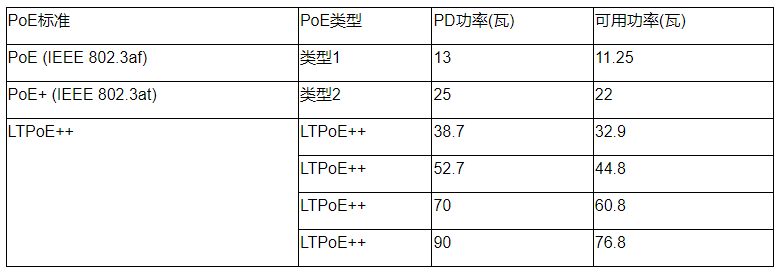
Power over Cat-5 cables is defined in the 802.3 Power over Ethernet standard. With PoE, Ethernet devices can receive power at the same time as the actual data transmission over the RJ45 cable. The PoE standard used to be limited to a few watts, but newer PoE technologies support higher powers. For example, PoE+ allows up to 25 W per port, while PoE++ (four-pair Power over Ethernet) ranges from 70 W to 100 W by using all existing cabling. In order to extend the benefits of PoE standards and give OEMs more flexibility, PoE manufacturers are developing parallel standards to provide more optimized methods for different applications. For example, Analog Devices has defined the LTPoE++ standard to support up to 90 W of powered device (PD) power (Table 1). Compared with similar solutions, LTPoE++ reduces the technical complexity of PoE systems. Other features of LTPoE++ include plug-and-play functionality, ease of implementation, and safe and reliable power supply. In addition, LTPoE++ is interoperable and backward compatible with IEEE's standard PoE specification. However, due to system loss and cable loss, the available power is slightly lower than the rated PD power, and the same is true for PoE+ and PoE+.
Table 1. PoE Standards

PoE components
Basically, powering a device over an Ethernet cable requires two components: a powered device and a power source equipment (PSE).

Figure 1. Block diagram showing the main components of a PoE system.
The task of PSE is to deliver power like a power source, while PD receives power and uses it (load). PSE devices have a signing process when they are powered on to protect non-compliant devices from being corrupted when they are connected. This involves first checking the characteristic resistance of the PD. Only when this value is correct (25kΩ) will the PD power up. If the PSE detects partial discharge, it starts with classification; that is, determining the power requirements of the connected equipment. To do this, the PSE applies a defined voltage and measures the resulting current. PDs are assigned to a power class based on current level. If all is well, full voltage and current will be provided. After the PD is powered, its task is to convert the PoE voltage of –48V into a power supply voltage suitable for terminal equipment. In a typical PD design, an additional DC-DC converter (diode bridge controller) is used. Its task is to adjust or meet the power requirements of the components provided by the PD. Newer ICs already offer the possibility to integrate the interface and dc-to-dc converter into a single low-power device, simplifying design.
PSE devices have a signing process when they are powered on to protect non-compliant devices from being corrupted when they are connected. This involves first checking the PD's signature resistor
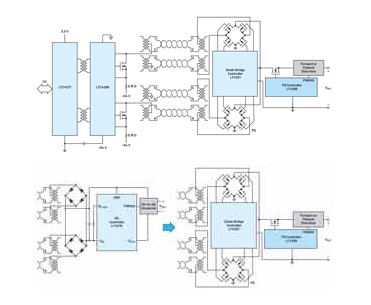
According to the IEEE802.3 PoE specification, the PD must accept DC operating voltage of any polarity at its Ethernet input, so two diode bridges are required in front of the PD's input. Therefore, the PD can also work with reversed polarity, independent of the wire pair used. Figure 2 shows LTPoE++ and PoE+ compliant PD controllers with integrated isolated switching regulators. Controllers such as the LT4276 support both forward and flyback topologies, and synchronous operation for power stages from 2 W to 90 W. Traditional PD controllers at lower power stages integrate power MOSFETs, but at higher powers, drive external MOSFETs The option enables the PD to reduce losses and increase efficiency.
Because the IEEE802.3 Ethernet specification requires electrical isolation from the ground connection of the device case, the system requires an isolated controller chipset for the PSE. The digital interface (LTC4271in in Figure 2) connects to the PSE host on the non-isolated side, while the Ethernet interface (LTC4290in in Figure 2) connects to the isolated side. The two components are connected via a simple ethernet transmitter. With this robust PSE chipset design, additional components for isolated power supplies can be avoided.
If the two diodes of the full-bridge rectifier on the PD side are replaced by ideal diodes, the power and efficiency of the entire PoE system can be improved. Therefore, MOSFETs are used and controlled to behave like typical diodes. In this way, the forward voltage can be significantly reduced due to the low channel resistance [RDS(ON)]. An ideal diode-bridge controller works with a PD controller to manage four MOSFETs in a full-bridge configuration (Figure 3).
Figure 2. Example PoE circuit.

Figure 3. Conventional diode rectification compared to driving through a diode bridge controller.
Standards developed in parallel, such as PoE and LTPoE++, connect smart factories and buildings while providing a robust end-to-end high-power approach to simplify the design and implementation of power supplies.