What happens when a browser enters a URL (4): Network packets are transmitted in the LAN – how routers and switches forward packets

In the previous section, we introduced that the network packet is encapsulated by the IP module of the protocol stack and sent out of the local machine through the network card.
Next, we'll look at what happens to the data that travels through the LAN after it is transferred from the client host.

After a network packet is sent out of the client host, it passes through hubs, switches, and routers and finally enters the Internet. In our real life, the router at home has integrated the functions of a hub and a switch, and the network packet can enter the Internet immediately after arriving at the router at home.
In order to understand the functions of hubs, switches, and routers, each function is introduced separately for easy understanding.
As shown in the figure below:
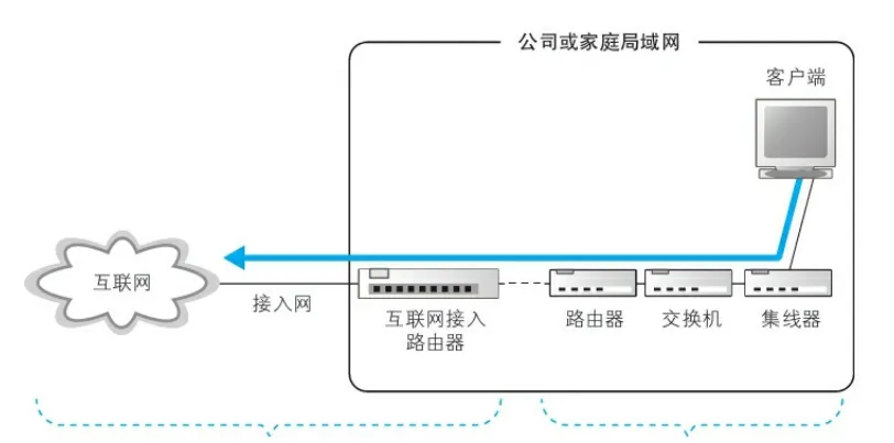
First, the electrical signal reaches the hub
As we know from the previous content, the computer network card will convert the data frame encapsulated by the MAC module into an electrical signal (a combination of 0 and 1 high and low levels), and the electrical signal will reach the hub along the network cable connected to the computer.
A hub contains multiple sockets (interfaces), each of which may be connected to other hubs, switches, routers, or multiple computers. Behind each interface is a module with the same function as the PHY (MUA) of the network card to receive and transmit electrical signals.
Each interface on the hub can transmit and receive, but each interface cannot transmit at the same time as it is transmitted, or at the same time as it is received, because the hub is based on a half-duplex mode of operation.
When the signal reaches the PHY (MUA) module behind the hub receiving interface through the network cable, it will enter the relay circuit, and the basic function of the relay circuit is to broadcast the input signal to all the interfaces of the hub, and the signal will be sent from these interfaces to all devices connected to the hub.
PS: The hub does not parse and process the data sent, that is, when the hub receives the electrical signal, it will not restore the electrical signal to digital information (that is, it will not restore the electrical signal to data frames and packets), but will directly forward the electrical signal.
Second, the electrical signal arrives from the hub to the switch
Switches, like hubs, have a number of interfaces, or ports, and each interface is followed by a PHY (MUA) module for receiving and receiving and generating signals. Different from the hub, the switch stores a corresponding table of MAC addresses and network cable ports (MAC address table) inside, and the switch is a device containing a data link layer, with a MAC module, which can check and parse data frames, while the hub does not, the hub will not convert the electrical signal into a data frame (but directly to the generated signal), let alone parse the data frame.
When the electrical signal is received by a port of the switch, the PHY (MUA) module restores the electrical signal to a data frame, and then the MAC module verifies whether the data in the data frame is correct (FCS check), and if it is correct, puts the Ethernet packet in the frame into the buffer.
PS: We can understand that each port of the switch is equivalent to a network card, with a MAC module and has its own buffer. In fact, not each port has its own PHY (MUA), MAC, and memory, but a single control chip controls multiple ports at the same time. And there is actually no NIC in the switch, so the switch does not have a MAC address either.
The NIC itself has a MAC address, so the NIC can check whether the MAC address of the receiver of the received packet is its own MAC address, and if not, it will drop the packet. However, since the switch does not have a network card and no MAC address, the switch will receive all packets sent to it and store them in the buffer and forward them without dropping them (if the interface corresponding to the sender's MAC address is the same as the interface corresponding to the receiver's MAC, the packet will be discarded, which will be described later).
After the packet is put into the buffer, the MAC module obtains the sender MAC address and receiver MAC address of the MAC header of the Ethernet packet.
On the one hand, the switch will record the mapping relationship between the sender's MAC address and the port number of the corresponding receiving port of the switch to the MAC address table, so that the switch knows which port the device with the sender's MAC address is connected to, and the next time another machine wants to send data to this MAC address, the switch will know which interface to send the data through.
On the other hand, the switch will query whether the receiver's MAC address is recorded in the MAC address table on the sending port, for example, if the receiver's MAC address is 00-02-B3-1C-9C-F9, it corresponds to the third row in the following MAC address table, and the switch will send packets from port 8.
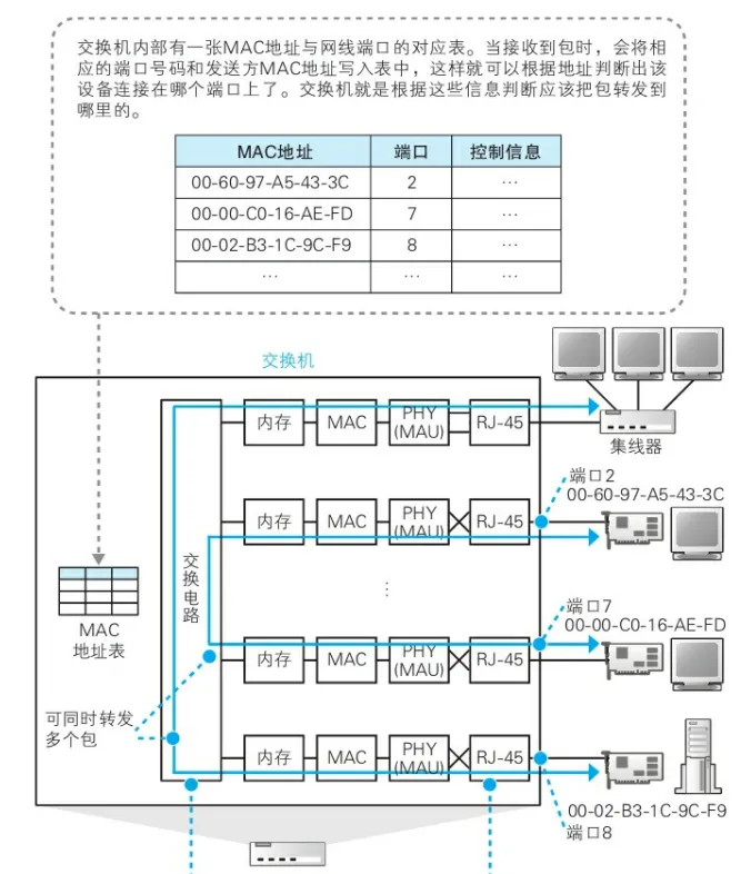
PS: If the switch receives a packet and its receiver MAC address is the MAC address of host A, the port where the switch receives the packet is not necessarily directly connected to host A, but may be connected to the hub that forwards packets for A or other switches that forward packets for A.
As you can see from the above figure, the ports of the switch are also divided into receiving ports and sending ports. The port number corresponding to the MAC address 00-02-B3-1C-9C-F9 is 8, then the transmit port number and the receive port number of the switch for this MAC address are both 8, but the send port and the output port themselves are not the same port, but two different ports, but their port numbers are 8. This involves the switching circuit of the switch. As shown in the figure below:
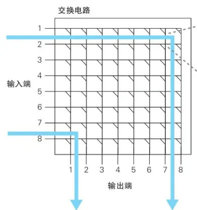
On the left is the input port of the switch, below is the output port, port 8 on the left is the receiver port of the switch to the 00-02-B3-1C-9C-F9 machine, and port 8 on the bottom is the send port of the switch to the 00-02-B3-1C-9C-F9 machine.
Maintenance of the MAC address table
As we mentioned earlier, when a packet is received, the switch records the sender's MAC address and the port number of the receiving port to the MAC address table, and the switch performs this operation every time it receives a packet. In this way, when a packet is received to this address, the switch will be able to send it to the correct port.
However, the records in the address table are not permanently valid and will be automatically deleted after a period of inactivity, in order to avoid situations similar to the situation where the records in the address table are no longer correct due to the movement of the device, such as the laptop moving from the office to the conference room with a different network cable.
Address table records are valid for a few minutes, but if a record becomes stale (a device move) within the validity period, the switch will still forward the packet to the old port and the communication will error. At this point, the switch is simply rebooted, and the address table is cleared and the correct information is updated.
Let's take a look at a special case: if the switch queries the MAC address table and finds that the interface corresponding to the receiver's MAC address and the sender's MAC address are the same in the record, what does the switch do?
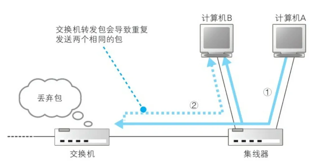
A sends a packet to B, and we find that A and B are connected to the same hub, and the hub broadcasts A's packet to all ports of that hub, including B. Therefore, after B receives the packet sent to him by the hub, he checks the MAC address and finds that it is his own MAC address, so B will respond to the packet, and the hub will send the packet back to A through the hub, and then the hub will send the packet back to A by broadcasting.
But the hub is also connected to the switch on the left, so the hub will also send this packet to the switch, the switch will check the MAC address table and find that the send port and the receive port are the same port number, in order to avoid computer B receiving duplicate packets, so the switch will drop the packet, and will not forward the packet back to the hub and the hub will forward it to B.
Another special case is that the specified MAC address cannot be found in the MAC address table because the device at the MAC address has not sent packets to the switch, or the MAC address record has been deleted because the expiration date has expired.
At this point, the switch forwards the packet to all ports except the source port. Some people may worry about whether sending too many packets will cause network congestion, but there is no need to worry, because as long as the target device responds (mainly referring to the ARP response), the switch will record its MAC address to the address table according to the packet, and there is no need to broadcast and forward it in this way next time.
Also, if the receiver MAC address is a broadcast address, then the switch will also send the packet to a port other than the source port.
The switch is a full-duplex mode of operation, which is also the difference between a switch and a hub. The transmit and receive ports of the switch are independent of each other, and the send port can only send but not receive, and the same is true for the receiving port. However, when the transmitting port is transmitting, the receiving port can also receive it, which is the characteristic of full-duplex mode. A single port of the hub can receive and transmit, but the receiving and transmitting cannot be carried out at the same time, otherwise a signal collision will occur, so when the hub receives a packet, it needs to forward the packet to all other ports, resulting in other ports not receiving packets during this period. In terms of forwarding capacity, hubs are lower than switches.
3. The network packet is forwarded through the router
Network packets are forwarded by hubs and switches to the router and are forwarded to the next router.
Of course, network packets do not necessarily have to go through the hub to the switch and then to the router, or the hub may be connected to the router, and the packets can be forwarded to the router after arriving at the hub; It may also be that the computer is directly connected to the router, and the network packet is sent from the computer and directly reaches the router. In the local area network, there are also many hubs and switches between routers and routers, and from the current router to the next-hop router, it needs to pass through the hubs and switches between the two routers; It is also possible that the router itself integrates the functions of a hub and a switch, so that the packet can be forwarded directly to the next-hop router in the manner described above.
Of course, the focus of this section is not on hubs and switches, but on the router's forwarding mechanism. Unlike switches, routers are designed based on IP (with a network layer and a link layer), while switches are designed based on Ethernet (only at the link layer), so the router can parse MAC packets and IP packets, while the switch can only parse MAC packets. The switch determines the forwarding destination based on the MAC address of the receiver in the packet, while the router determines the forwarding destination based on the IP address of the receiver in the packet.
1. Simplified diagram of router structure

The router consists of two parts: a forwarding module and a port module.
转发模块负责根据包内目的地IP判断包应该转发到哪个下一跳路由器;端口模块负责执行包的收发操作。
2.端口模块
端口模块包含PHY(MUA)模块(可以接收电信号将帧转为数字信息)、MAC模块(将帧解析为以太网包)和内存缓冲区(暂存网络数据),端口模块对于路由器而言就相当于网卡对于计算机一样。路由器的每个端口都具有独立的MAC地址和IP地址。
Different types of routers have different port modules, such as routers with ADSL components (generally used as routers in the Internet), routers with FTTH components (routers in the Internet), routers that support private line (routers in corporate LANs), and routers that support wireless LAN or Ethernet (routers in LANs).
Routers with different port modules support different communication functions, for example, a router with ADSL communication function will add MAC headers, PPPOE headers, and PPP headers (for transmission and authentication in the Internet) to the packets before forwarding them and send them to the Internet; Routers with Ethernet or Wi-Fi functions only add MAC headers when forwarding, and only support packet transmission and resolution within the LAN.
Generally speaking, the network card of the computer supports the communication technology of Ethernet and unlimited LAN, and the port module of the router supports the communication of such as ADSL, FTTH and various broadband private lines in addition to supporting Ethernet and wireless LAN, and only needs the port module to install the hardware that supports these technologies.
A router can have multiple ports and multiple types of ports (meaning that the router supports both packet forwarding in the LAN and the Internet), each port may be connected to a network cable (if the port type is wireless, no network cable is used), and different port types are connected to different types of network cables.
3. Forwarding module
There is an important table in the forwarding module of the router called the routing table, which is as follows:
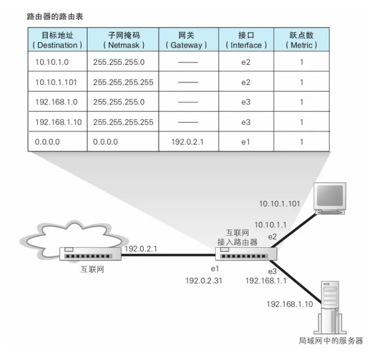
The contents of the routing table and matching rules in the router are the same as those in the computer described earlier.
Among them, the first column of "destination address" records the information of the receiver, but it is not the IP of a specific device, but only the IP range of the network number part of the IP, which means that the bit value of the host number part is 0.
The second column represents the subnet mask of the destination address, which is used by the router to determine the number of bits of the network number to be compared.
When the router compares the routing table with the receiver IP, it only compares the network number of the receiver IP and ignores the host number.
4. Route aggregation
The records in the first and second columns of the routing table may not be the true subnet of the destination address IP, which is the result of route aggregation. The so-called route aggregation is to merge multiple subnets into one subnet and generate a record in the routing table, which can reduce the number of records in the routing table.
For example, there are 3 subnets: 10.10.1.0/24, 10.10.2.0/24, and 10.10.3.0/24. Router B needs to forward packets with the receiver's IP address 10.10.2.100, but in fact, Router B does not have the above three subnets in the routing table, but merges the above three subnets into a 10.10.0.0/16 subnet (here the aggregated address is recorded), and points the next hop to Router A. It looks like this:
Destination address | Subnet mask | gateway | interface | Number of hops |
10.10.0.0 | 255.255.0.0 | IP of Router A | The IP address of an interface of Router B | 1 |
In this case, only the first 16 bits of the destination address 10.10.2.100 need to be matched in router B, that is, 10.10. After the match is correct, B forwards the packet to Router A.
The routing table of Router A records the above three subnets, and matches the IP addresses of the subnet 10.10.2.0/24 and the next hop according to 10.10.2.100, as follows:
Destination address | Subnet mask | gateway | interface | Number of hops |
10.10.1.0 | 255.255.255.0 | ... | IP of port 5 of Router A | 1 |
10.10.2.0 | 255.255.255.0 | ... | IP address of port 2 of Router A | 1 |
10.10.3.0 | 255.255.255.0 | ... | The IP of port 8 of Router A | 1 |
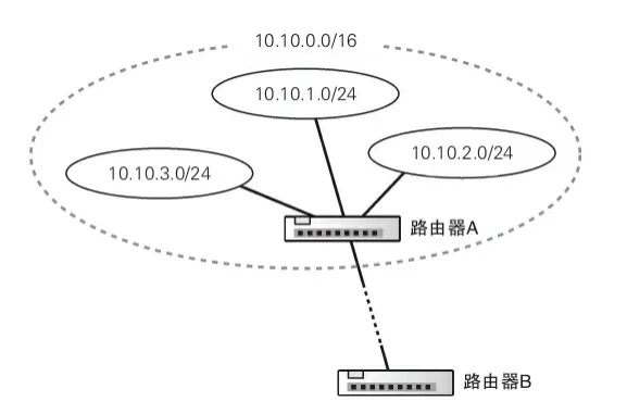
Route aggregation is to aggregate multiple subnets into a single subnet, and the route table records the subnet addresses after the aggregation. Conversely, a router may also subdivide a subnet and register it with a routing table to form multiple records. You can even write the address of a specific computer to a route, and the subnet mask in the second column is 255.255.255.255, which means that all 32 bits need to be matched to match the routing table.
As for the gateways, interfaces, and hop counts, the routing table of the computer introduced above has already been introduced, so I will not repeat it here. Column 4 represents a network card in a computer and a port in a router that is one of the many ports on the router.
PS: The maintenance mode of the routing table is different from that of the switch, and the maintenance of the MAC address table by the switch is implemented by recording the MAC address of the Ethernet packet of the sender and the port number of the receiving port of the switch, the MAC header of the response Ethernet packet of the receiver, and the receiving port of the switch receiving the packet. The maintenance of the routing table is maintained manually by humans and by the routers themselves through the exchange of information between routers according to the routing protocol.
So back to the topic, what does the router do when the packet arrives at the router, which will vary according to the router's port (such as Ethernet port, wireless LAN port, ADSL, etc.), here only introduces how the router's Ethernet port receives and forwards packets.
First, the signal arrives at the network cable interface part, and the PHY (MUA) module and the MAC module convert the electrical signal into digital information, check the FCS at the end of the frame, check whether the MAC address of the receiver is sent to itself, and put it into the receiving buffer. Packets that are not sent to themselves are discarded (the switch does not have a MAC address and is only responsible for forwarding, so the switch does not drop the Ethernet packet because it verifies that the MAC address is not its own, but forwards it according to the MAC address table).
After the MAC address is verified, the MAC header is completed and then discarded (the task of the MAC header is to send the packet to the router with the specified MAC address, so in fact, in the previous chapter, we introduced that broadcasting to the LAN through the ARP protocol to obtain the MAC address of the receiver is actually obtaining the MAC address of the router instead of the MAC address of the remote destination host). The router then matches the records in the routing table based on the receiver IP address in the header of the IP packet, so as to find the IP (that is, the gateway column in the routing table) and the output port (the interface column of the routing table, that is, through which port of the router the packet is sent out). Note that if the gateway of the matched record is listed as a specific IP address, that address is the next forwarding destination, and if the gateway is listed as empty, the receiver IP address of the IP header is the next forwarding destination.
If the corresponding record cannot be matched in the routing table, the router discards the packet and notifies the sender through an ICMP message.
Before sending this packet, the router needs to re-encapsulate the MAC header because the previous MAC header has been discarded. In this case, the sender's MAC address entered in the MAC header is not the MAC address of the source sender, but the MAC address of a sending port of the router (the router has multiple ports, and each port has a MAC address). The MAC address of the receiver is obtained by ARP query based on the IP of the next forwarding destination (which may be the IP of the next-hop router or the IP of the destination host).
After the network packet is encapsulated, the digital information will be converted into an electrical signal and sent out in the port module, which is the same process as sending packets on the computer. If the output port is of the Ethernet type, the network packets will pass through the switch to the next router and be forwarded through the router, and the network packets will reach the final destination (of course, the process of how packets enter the Internet from the LAN is omitted here, and we will cover it in the next chapter).
It should be noted that if the router sends packets through an Ethernet port, the Ethernet packet header is only the MAC header, and if the packet is sent through an ADSL port (sending the packet to the network service provider and the Internet), the Ethernet packet will contain the MAC, PPPoE, and PPP headers.
5. Default route
For routers in a LAN, there may not be a large number of routers and computers in a small LAN, so all forwarding destinations can be written to the routing table. However, if it is a router in the Internet, the network number of all destination IPs cannot be recorded in the routing table due to the large number of devices in the Internet. Therefore, the routing table will configure the default route record in the last row, and the destination address column and subnet mask of this row are listed as 0.0.0.0, and the subnet mask is 0.0.0.0, which means that the number of bits that need to match the IP of the receiver of the network packet is 0, that is, no matching is required. The gateway column of this record is the default gateway, which is usually filled in as the address of the router that connects to the Internet.
In other words, if the receiver IP in the packet cannot match all other records in the routing table, and there is a default gateway record of 0.0.0.0 in the routing table, the receiver IP will match this record and be forwarded to the default gateway.
Of course, if there is no default gateway set in the router, then the router will send an ICMP message to the sender when all records in the matching routing table fail.
6. Expiration date of the package
Before the router forwards the packet, its forwarding module updates the TTL field of the IP header. This field indicates the expiration date, and the value will be reduced by 1 for each forwarding by a router, and when this value becomes 0, it means that the expiration date has been exceeded, and the packet will be discarded.
This mechanism is to prevent packets from falling into an endless loop in the process of forwarding, which will not occur if the configuration in the routing table is correct, but will occur if there is a problem with the information or a device failure and the standby router is temporarily confused.
The TTL is usually set to 64 or 128.
7. Split large network packets through the sharding function
The port type of the router is not only Ethernet, but also supports other LAN or private line communication technologies. The maximum packet length (MTU) that can be transmitted by a line varies depending on the port type, for example, in Ethernet, the MTU (including the Ethernet header) of an Ethernet packet is 1500.
When the input port and output port of the router are of different port types (for example, the input port and output port of the router in the LAN may be Ethernet ports and lines, but the input port of the router connected to the Internet is an Ethernet port and the output port is an ADSL port), and the MTU that can be transmitted by the output port is smaller than the input port, once the size of the incoming packet exceeds the MTU of the output port, the packet will not be sent. It is shown below

Sometimes, even though the MTU of the input and output ports is the same, the length of the packet may exceed the MTU of the output port due to the addition of additional header data after the packet has been re-encapsulated. For example, for port types such as ADSL and FTTH, you need to add a PPP header and a PPPoE header before sending packets, and then add a MAC address header before sending packets.
In order to avoid the situation that the packet exceeds the MTU of the output port and cannot send the packet, the IP module in the router provides the fragmentation function, first it will see if the packet to be sent out can be sent directly, compare the MTU of the output port with the length of the packet (the packet length of the data frame, excluding the header and FCS of the frame), if the MTU of the output port is less than the length of the packet, the packet will be fragmented, and before splitting, it will look at whether the flag field of the IP header allows fragmentation; If the flag field indicates that fragmentation is not possible, the router drops the packet and sends an ICMP message to the sender.
The sharding is shown in the following figure:
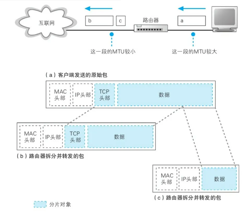
图中(a)的蓝色部分就是被拆分的内容
每个分片都会添加相同的MAC头部和IP头部(如果是在以太网中传输则为这两个头部,如果是通过ADSL则还需要PPP和PPPoE头部)。
需要注意的是,这里对IP包的分片和之前在协议栈中介绍的TCP模块对HTTP消息的分片不同。TCP模块对HTTP消息的分片是在数据被装进包里之前进行的,而且每个分片都包含一个TCP头部。而路由器则是直接对IP包进行分片,每个分片都有一个IP头部,但是所有分片只有一个TCP头部。TCP分片也是因为要发送的数据可能大于MTU因而分片。
假如有客户端有1M的http消息要发送,则这1M的内容会在TCP模块中被分为几百多个分片包(IP包),但经过路由器的时候,每个IP包还可能再被路由器的IP模块分片为两个小包。
8.路由器与交换机以及路由器之间的关系
简单的来说,路由器负责通过将包不断传递给下一跳路由器最终把包送达通信对象这一整个过程(由网络层如IP模块负责)。而包从一个路由器到达下一个路由器则是由交换机负责广播获取MAC地址实现(由链路层如以太网线路等负责)。
网络中除了以太网之外,还有无线局域网、ADSL和FTTH等等众多类型的网络,如果当前路由器和下一跳路由器是通过以太网连接的,则当前路由器的IP模块会委托以太网将包传递给下一个路由器;如果当前路由器和下一跳路由器是通过ADSL连接,则会委托ADSL线路传递。IP本身不负责包的传输,而是委托链路层的各种通信技术(以太网、ADSL、FTTH、无线局域网等)把包传给下一个路由器。
当然,现在基本上很多的路由器都内置了交换机功能,因此路由器本身就具有广播,以及进行ARP查询MAC地址的功能。
四、路由器的附加功能
上面我们介绍了路由器的基本功能,即根据网络包头部接收方IP来查询路由表,获取下一跳地址,并以接力的方式将包传送到目标地址的计算机上。
除了这个基本功能之外,路由器还有一些附加功能,这里介绍比较重要的两个功能:地址转换和过滤。
1.地址转换
我们知道一台设备只有一个唯一的IP地址,如果网络中出现有重复IP地址的设备就会无法正常传输网络包。可是随着互联网设备数量增长,IP地址会被很快分配完。为了解决这个问题,我们容许相互独立的不同内网之间的机器出现IP重复而同一内网的机器的IP不重复的情况,只要不同内网之间的设备不直接进行通信就行。为此我们提出了私有地址和公有地址的概念。
公有地址中没分配的一部分拿出来规定只能在内网使用的地址叫做私有地址,而互联网中分配的固定地址叫做公有地址。
私有地址的范围如下:
- 10.0.0.0 ~ 10.255.255.255
- 172.16.0.0 ~ 172.31.255.255
- 192.168.0.0 ~ 192.168.255.255
不同内网的两台机器即使出现上面范围内的IP地址重复也没有关系。
Let's take the company's intranet as an example. Generally speaking, the equipment in the company's intranet is divided into two parts, one is the server that is open to the Internet, and the other is the company's internal equipment. Devices that are open to the Internet are assigned public addresses, and devices within the company are assigned private addresses, and devices that are assigned private addresses can only communicate directly with devices on the intranet network and cannot directly send and receive network packets with the Internet.
If a device in the intranet wants to communicate with a device on the Internet, it needs a special mechanism, which is address translation.
The principle of address translation is to rely on the router to rewrite the IP address and port of the IP packet header when forwarding network packets.
When the intranet device wants to send the network packet to the remote target machine, when the network packet passes through the router, the router will replace the sender's IP address (private address) in the IP packet header with the address of the router's receiving port (the port address of the router is a public address), and rewrite the port number of the packet TCP header to a free port number assigned by the router.
The private address and port number before the rewrite, and the public address and port number after the rewrite will be recorded in a table on the router.
The replaced public address is actually the IP of the address translation device, i.e., the IP of the router. So in fact, the real sender is not the computer on the internal network, but the router.
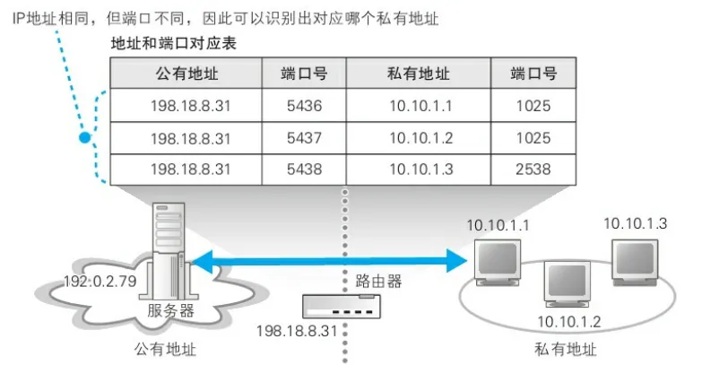
The receiver IP address of the server's packet will write the public address of the sender, that is, 198.18.8.31, which is the IP address of the router. When the packet arrives at the corporate gateway router, the router will check the mapping table above to find the corresponding intranet device and forward it to the device based on the receiver IP and port of the return packet (there is only one public IP in the table above, but the real situation may actually have multiple public addresses because the router has multiple ports).
If there is only one public address, you can use different port numbers to distinguish different terminals on the intranet. In this way, the server-side packet cannot find the accurate intranet device.
A record of the mapping table between public and private addresses will be generated when a connection is established between an intranet computer A and an extranet server B (when the TCP packet sent by A to the connection request arrives at the router), and then the communication between the intranet computer A and the extranet device B will use this conversion record until A and B complete the communication, disconnect, and A closes the socket used to communicate with B, (at this time, the port number of the private address is invalid).
We found that the router also rewrote the port number when doing address translation, which is to make a port number of the public address correspond to a private IP address during address translation, so as to improve the utilization of the public address. If you don't rewrite the port number, it means that a new public address is needed for every private address you convert. If the company's LAN is assigned only 10 public addresses, but the company has 1,000 devices (1,000 private addresses), this means that only 10 internal devices can communicate with the Internet at the same time.
We described router address translation when the intranet device acts as the client and the remote device in the Internet acts as the server. Next, let's talk about the address translation of the router when the company's intranet device acts as a server and accesses the company's intranet device from the Internet.
In fact, the basic principle is to reuse multiple port numbers of one (or more) public addresses to establish a map for conversion corresponding to multiple private addresses, the only difference is that when the intranet device is a client request, the record of this address translation table is generated when the device makes a request and passes through the router (i.e., dynamically generated); In the case that the intranet device serves as a server for Internet requests, the address translation table records in the router need to be manually added in advance, and as long as the intranet device does not stop providing services, the records in it will not be deleted. As shown in the figure:

这样一来,互联网中的某个用户访问198.18.8.31:8080其实访问的就是公司内网中的 10.10.1.1这台机器的80端口所提供的服务。
2.路由器的包过滤功能
Packet filtering is to forward packets based on the time-limited rules set by MAC address, IP header, and TCP header to decide whether to forward the packet or discard the packet. What we often call firewall devices and software makes use of this mechanism.
Although this principle is simple, it is not easy to flexibly control, for example, how to prevent packets from the Internet from entering the intranet through the router, but also allow packets sent from the intranet to be forwarded to the Internet through the router.
Many friends will think that if you want the intranet to access the Internet without allowing the Internet to access the intranet, you only need to allow the router to forward packets sent from the intranet to the Internet, and prohibit forwarding of packets sent from the Internet to the intranet.
However, network packets are transmitted in both directions, for example, in the TCP reply mechanism, when the intranet device sends a network packet with an order number, the server will return an ACK packet. In this case, the ACK packet is intercepted, resulting in the failure to respond to the request sent to the client from the intranet (it should be said that the client's request packet cannot be transmitted normally, and the client host will wait for the reply packet from the server).
This will be covered when exploring servers.