Ctrip Optical Network’s practice of resisting optical cable interruptions

Ctrip Optical Network’s practice of resisting optical cable interruptions
About the Author
Lightworker, a Ctrip network technology expert, focuses on the fields of optical fiber communications and DCI transmission technology.
1. Background
Optical transmission network (OTN for short) is a communication network based on optical fiber technology. It uses optical fiber as the transmission medium to transmit information in the form of light. It relies on DWDM (Dense Wavelength Division Multiplexing) technology and protection switching technology to achieve large bandwidth, low latency, and highly reliable data transmission, so it is widely used in multiple data center interconnection scenarios. Large domestic and foreign Internet companies build their own transmission networks by renting optical fiber from operators, which can greatly reduce the cost of data transmission between IDCs. Similarly, Ctrip also has its own self-built optical transmission network (TOTN), which is mainly used to carry backbone network cross-data center traffic and IT office Internet traffic.
As the underlying physical network, TOTN directly faces operator optical cables and needs to deal with frequent optical cable failures. As we all know, domestic infrastructure is still in the development stage, and operator optical cables are often dug out during construction. According to statistics from US operator Level3, its optical fiber network is interrupted approximately once every 1,000 kilometers per year; China Telecom probably experiences more than 50 trunk optical cable interruptions each year; and in India, there are several or even more than a dozen interruptions almost every day. It can be seen that the number of optical cable interruptions is closely related to the degree of local social and economic development.
Since its establishment, Ctrip TOTN has detected an average of more than 20 optical cable interruptions every year. Therefore, while providing large-capacity transmission, if the optical network can automatically switch when an optical cable failure occurs, the business bandwidth will not be affected, and the failure will not even be detected, which will greatly improve network reliability.

Figure 1 Optical cable cutting site
2. Overall structure
Ctrip's transmission network is designed with dual plane protection. Each IDC deploys two completely independent sets of transmission equipment and connects two optical fibers with different routes to form two completely independent transmission planes.
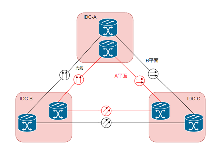
Figure 2 TOTN topology diagram
Under normal conditions, the business travels on the direct link. When the main optical cable is interrupted, the transmission system will switch the business to the backup channel to bypass it. The active and backup channel switching time follows the ITU-TG.783 and ITU-TG.841 standards and is less than 50ms.
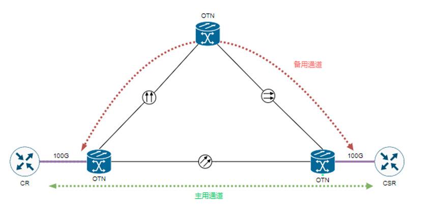
Figure 3 Optical network protection

Figure 4 Business flow when optical cable fails
Through the above protection mechanism, it can solve the problem of automatic switching of services when the optical cable is interrupted, without losing bandwidth, and resist the extreme situation of two optical cable interruptions occurring at the same time.
But at the same time, there is a problem that has been bothering us, that is, flapping exists on the network device ports at both ends during transmission switching, resulting in corresponding error reports in the business.
3. Problem analysis
The time from down to up for the network device interface is different due to different devices and different optical modules, and the convergence time of layer 2 and layer 3 of the network layer has uncertain factors due to different network architectures (usually considered to be a second-level interruption), so each time Transmission switching will cause services to be unavailable for a certain period of time. Usually manifested in error reports of sensitive businesses, such as Redis. As an in-memory database, Redis is very sensitive to network jitter, and is aware of almost every fiber optic cable interruption and switching.
For example, at 12:00 on March 17, when transmitting plane A, the optical fiber was interrupted and the CSR in direction of the backbone network was wrong.

Figure 5 Backbone network error report
For example, at 19:44 on September 11, the B-plane optical cable was interrupted, and Redis reported a large number of errors during transmission switching, as shown below:
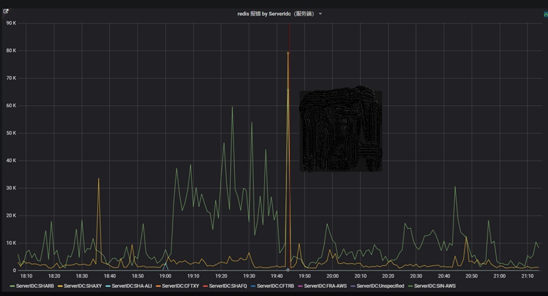
Figure 6 Redis error report
To solve the problem of network device port flapping caused by transmission switching, the industry has not yet had a mature standard solution. Through research on other Internet companies, a common solution is to configure link-delay on the switch interface. That is, after the router receives the link interruption signal, it delays for a period of time to set the link status to down. During this period , if the link recovers, the link up state is maintained and the down state is not generated, thus avoiding frequent link jitters.
We also tried this method, but found that there were problems such as the device was not supported, the configuration did not take effect, etc., and we were unable to achieve the expected results. The reason is that link delay is not an IEEE standard, and network equipment from different manufacturers have different support for this function. For this reason, the distribution of transmission services can only be allocated to different optical cable routes to ensure that at least half of the services are not affected when the optical cable is interrupted, but this cannot always solve the problem of service awareness. For example, if 200G services need to be activated from terminal A to terminal Z, they must be allocated to two different planes, and each 100G service participates in the switching of its own plane.
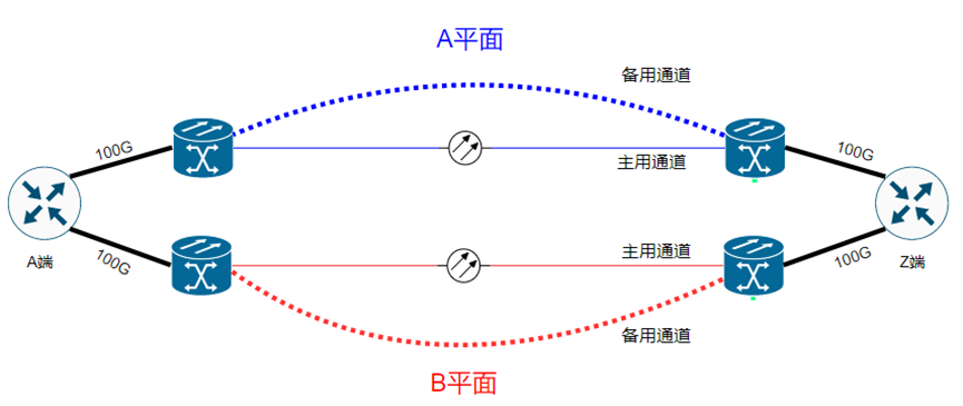
Figure 7 Business allocation diagram
In addition, during our research, we found that some companies set the delay to 2 seconds in order to make link-delay effective. Although such a setting enables transmission protection switching to take effect, once the protection mechanism fails, 2 seconds of precious time will be lost in the switching at the routing level.
4. Technical Research
In 2023, TOTN will introduce a DCI product that supports 5ms switching. This product will increase the transmission switching time of 50ms to 5ms through two improvements. The first is the application of a magneto-optical switch. The principle of the magneto-optical switch is to use the Faraday optical rotation effect to change the effect of the magneto-optical crystal on the polarization plane of the incident polarized light through changes in the external magnetic field, thereby switching the light path. Since there are no mechanical moving parts, it has high reliability and fast switching speed; secondly, by pre-entering the optical cable parameters of the backup channel into the DSP chip, it saves the time of recalculating parameters during switching.
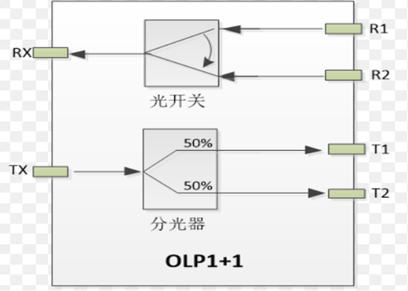
Figure 8 Principle of optical switch
We hope to solve the problem of network device port flapping by shortening the time of optical switch switching. However, in actual applications, even if the transmission switching time has been compressed to 5ms, the ports of the network equipment will still flapping. After researching and debugging the product parameters, we found that when the optical cable is interrupted, the transmission optical layer will send AIS signals to the electrical layer boards at both ends. After receiving the AIS signals, the electrical layer boards will send a Local_Fault alarm to the network equipment. When the network device receives this alarm, the port becomes down (IEEE 802.3ae). By setting the transmission system delay to send this signal (default 4*50ms), as long as the transmission switching is completed within this time period, the signal will not be sent to the network device, so the port will not flapping.

Figure 9 Schematic diagram of fault signal transmission
After DCI products successfully achieve handover-free perception, we hope to find similar parameters for adjustment in traditional products on the existing network. Because the alarm delay transmission has nothing to do with the 5ms switching time, even if the switching time is 50ms, if the network equipment port can not sense the jitter of the optical cable, it will greatly improve the business stability.
5. Optimization plan
In order to enable traditional network products to support seamless switching, through technical communication with the manufacturer, we came to the conclusion that the 100GE service mapping method needs to be adjusted from BIT transparent mapping to MAC transparent mapping (which will interrupt the service), and then set the alarm parameter delay of 200ms. transfer.
Since TOTN has never used MAC transparent mapping, we coordinated with the equipment manufacturers to conduct special testing and verification of MAC mapping and BIT mapping in the laboratory. The conclusion is that there is no difference in throughput between the two methods, but there is a difference in delay. During BIT mapping, the frame length of 64-9600Byte is 24us. During MAC mapping, it increases with the frame length, but when the maximum is 9600, it is 25us. It can can be ignored.
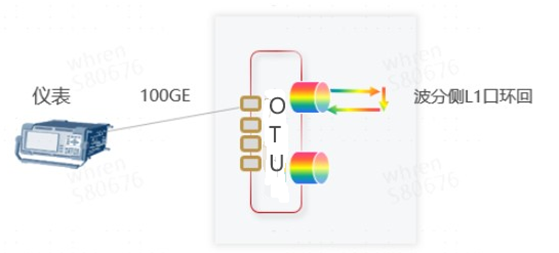
Figure 10 Experimental environment topology
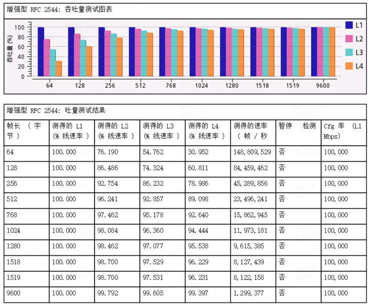
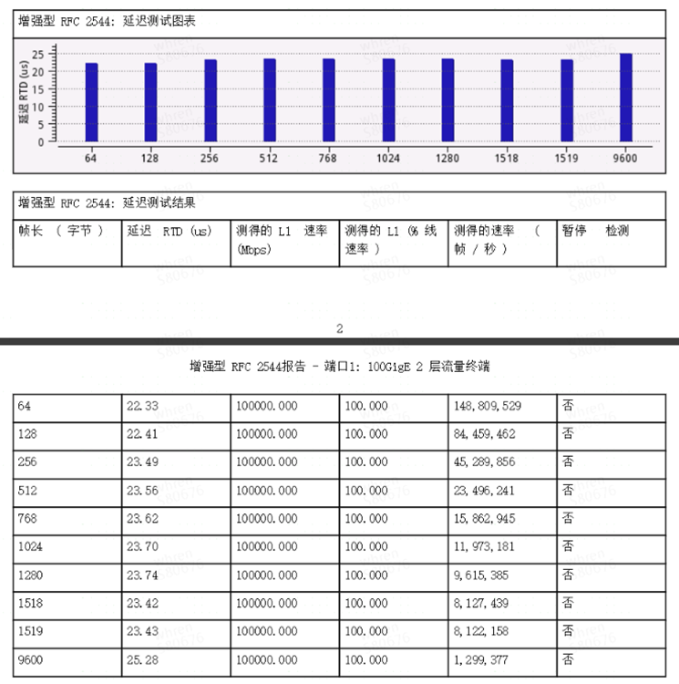
Figure 11 RFC2544 test results
Therefore, we formulated an optimization plan, first adjusting the transmission plane A, and then adjusting the B plane after the grayscale operation for a period of time.
6. Verification effect
On August 18, the transmission plane A was optimized: the 100GE service mapping method adopts MAC transparent mapping, and the alarm parameters are transmitted with a delay of 200ms. After testing, it has been verified that the main and backup switching of the transmission optical cable can be realized without being aware of the network device ports, and Redis is unaware.
It has also been verified in real failure scenarios. For example, an optical cable interruption occurred on the transmission plane A at 15:13 on September 7, and Redis reported no abnormal spikes.
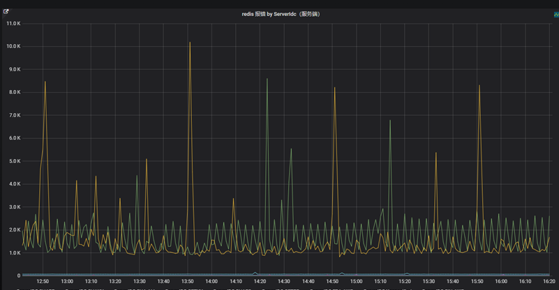
Figure 12 Redis error after optimization
After a month of grayscale verification, we optimized the transmission B plane on September 15, and further shortened the alarm parameter delay transmission time from 200ms to 100ms. It has also been tested and verified that Redis is imperceptible.
7. Future planning
In order to maintain the unity of the architecture, we will redefine Ctrip's optical network equipment technical standards and require that newly added OTN equipment must support BIT-mapped alarm delayed insertion. At the same time, all suppliers are encouraged to fully support this function, making it a best practice in optical cable failure scenarios.
Resisting optical cable failures is a recognized problem in the industry, and leading Internet companies have stumbled here. Through the above series of practices, we have achieved a leading level in resisting optical cable failures. Optical network operation and maintenance is a long-term process, and unaware switching is only a small part of it. More is alarm discovery, performance monitoring, and optical cable route identification to avoid the occurrence of the same route.