No more worries about network faults: Learn about Ethernet interface physical DOWN faults and solutions in one article!
No more worries about network faults: Learn about Ethernet interface physical DOWN faults and solutions in one article!
1. Concept of interface physical Down
The Ethernet interface is a real, device-supported physical interface provided for user operation or configuration. It is mainly used to receive and send data. Keeping the interface in a normal UP state is the most basic condition for the normal operation of the device.
When the interface is in the DOWN state, its indicator light is always off, the interface cannot receive packets normally, and a log similar to the following format is generated on the device:
IFPDT/4/IF_STATE(l)[3]:Interface GigabitEthernet0/0/12 has turned into DOWN state. - 1.
You can run the display interface command to view the current physical status of the interface (the current state field information in the echo).
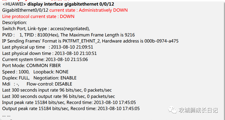
In the example in the figure above, the current physical status of interface GE0/0/12 is Administratively DOWN, that is, the shutdown command exists under the device interface. It can be concluded that the configuration error causes the interface DOWN. You need to execute the undo shutdown command under the corresponding interface plan.
2. Interface physical DOWN causes and solutions
The causes of interface physical DOWN mainly include hardware and software faults:
- Hardware failure: Hardware failure of the local or peer device includes failures of single boards, interfaces, optical modules, optical fibers, network cables, etc.
- Software failure: Mainly includes inconsistent configurations at both ends of the link, including port negotiation mode, speed, duplex and other configurations.
As shown in the figure below, in order to more accurately analyze the cause of the physical DOWN failure of the interface, this article mainly uses the possible introduction points of the fault as clues, and specifically follows the five steps of man->machine->material->method->ring five steps as the troubleshooting sequence, step by step Find the root cause of the problem and troubleshoot it.
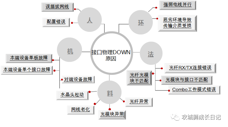
Interface physical DOWN
1. Human - Human factors cause the physical DOWN of the interface
(1) Description of fault cause
When the door changes from the normal UP state to the physical DOWN state, you need to first check for any recent human operations, including incorrect plugging and unplugging of network cables, accidentally touching the device causing the connection to become loose, and misoperation of the command line on the device.
(2) Trouble diagnosis operation steps
Run the displayinterface interface-type interface-number command in any view on the two connected devices to view the current running status and interface statistics of the interface. As shown in Figure 3, focus on the red fields in the following echo
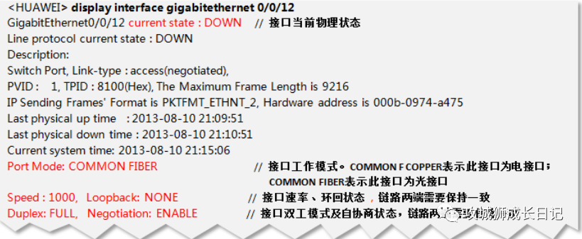
- If the current state field is "Administratively down", it means that the interface has been shut down manually. Please execute the undo shutdown command on the interface.
- If the current state field is "DOWN", you need to check whether the rate, duplex, and auto-negotiation mode are consistent at both ends of the link.
- If the Negotiation field is "ENABLE", the interface is in auto-negotiation mode, and the rate and duplex are negotiated by both parties. If the rate and duplex negotiation at both ends of the link are inconsistent, you can execute the restart command to restart the interface and renegotiate it. If the negotiation still fails, run the undenegotiation auto command to make it work in non-auto-negotiation mode. See the next situation for rate duplex configuration.
- If the Negotiation field is DISABLE, the interface is in non-auto-negotiation mode. To double the rate, you can execute speed[10|100|1000] and duplex{full half} in the interface view to keep the parameters consistent at both ends of the link.
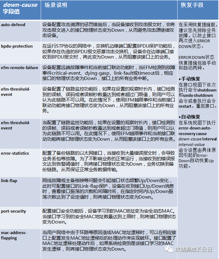
- If the current state field is ERROR DOWN (down-cause), it means that the interface was shut down due to an error event. You need to troubleshoot the fault based on the specific down-cause field information. Common down-cause field values are as shown in the figure below.
(3) "Fault recovery method
Batch interface physical DOWN:
- If multiple interfaces are physically DOWN, and these interfaces all belong to the same board and are connected to multiple peer devices without exception, the board may be abnormal. Try executing the reset slot slot-id command to reset the board. If the fault is still not resolved, the board needs to be replaced
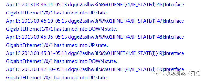
- If multiple interfaces are physically DOWN, and these interfaces are connected to the same device on the local device and the peer device, the possible cause is that the peer device is abnormal. You need to log in to the peer device to check whether the device board is faulty, and perform repairs in a timely manner. During a reset or replacement operation, if the peer device is in active/standby switchover, hibernation, restart, etc., it can be considered a normal phenomenon. After the peer device is stabilized, the interface status of the local device will automatically return to the UP state. . Under this field number, the interface will frequently UP/DOWN, resulting in a large number of UP/DOWN logs as shown below.
A single interface is physically DOWN: If there is only a single interface that is physically DOWN, you need to check whether the interfaces at both ends of the link have hardware faults such as metal shrapnel dents. If the interface is faulty, you can try to use other idle interfaces.
2. Material-connection medium failure
(1) Description of fault cause
The physical interface of the switch includes electrical ports and optical ports, and the transmission media involved are mainly RJ45-network cables, optical modules, and optical fibers. When the transmission medium is aged, damaged, or the optical module receives and receives abnormal light, it will cause the interface to physically go down.
(2) Trouble diagnosis operation steps
Electrical port connection medium failure:
- Check whether the connection is correct: Ensure that the interfaces at both ends use the same network cable. If it passes through a jumper rack, please check whether the jumper is correct, check whether the interface is connected correctly, and check whether there is poor contact or external damage to the network cable.
- Check whether the network cable specifications and length meet the standards: According to Ethernet related standards, the network cable length cannot exceed 100m. For the GE electrical port, if you use a network cable lower than Category 5 cable, you will not be able to make the GE electrical port Up at the 1000M rate. For all electrical port connections, it is recommended to use network cables with Category 5 cable or above.
- Check whether the status of the internal wire pairs of the network cable is normal: if some of the 4 pairs of wires in the network cable are damaged, the normal UP of the electrical port cannot be guaranteed. To check the quality of the network cable, you can use a line tester or execute the virtual-cable-test command in the interface view to check whether the line sequence pair connection is normal.
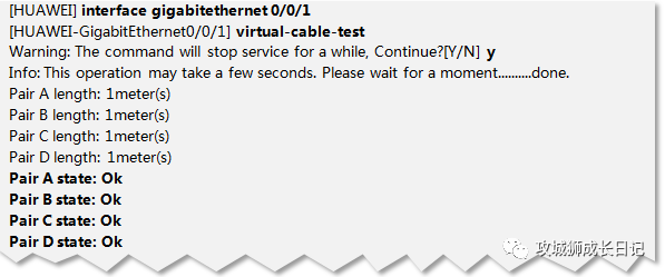
As shown in the figure above, if the Pair state in the echo is OK, it means it is normal; if it is in other states (such as Open or short), it is recommended that you change other network cables to test. "
Optical port connection medium failure:
- Whether the optical module is a Huawei-certified optical module: Huawei adds the Huawei logo and corresponding logo to the optical module label shipped by the switch product, as shown in Figure 7. The product electronic label and optical module information are updated to "HUAWVEI" Manufacturer Information: When optical modules shipped without Huawei certification are inserted into switch equipment, an alarm message will appear. The alarm format is as follows:
ENTITYTRAP/3/OPTICALINVALID:OID oid] Optical Module is invalid.(Index=INTEGER),
EntityPhysicalIndex=INTEGER), PhysicalName= "OCTET", EntityTrapFaultID=[INTEGERJ)- 1.
- 2.
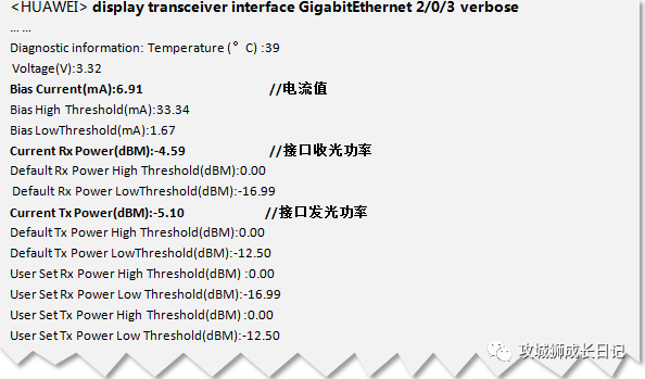
- 检查光模块状态是否正常:执行命令display transceiverinterface,检查两端设备上的光模块工作状态是否正常,主要查看收光功率、发光功率、电流值等,确定各项指标是否都在正常范围内。
(3) 故障恢复方法
电口连接介质故障:如果电口网线故障,建议直接更换网线
光口连接介质故障:
- 如果使用的光模块为非华为认证光模块,请更换使用华为认证光模块。非认证光模块可靠性无法保证,可能导致业务不稳定。由非华为认证光模块导致的问题,华为将不承担责任,并在原则上不予以解决。
- 如果执行display transceiverinterface命令查看光模块工作状态参数,按照表1所示标准结论判断参数否超出正常范围。
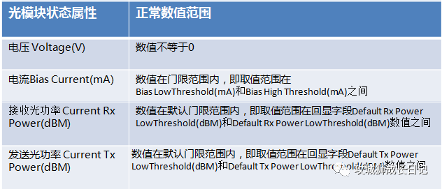
- 如果发送光功率过低或过高:请更换光模块
- 如果收光功率过低或过高:使用光功率计测试链路各部分的光功率亮减情况,对异常的部位进行修复。
- 如果仍无法解决问题请更换光模块或者光纤,确保光模块传输距离和光纤类型符合组网需求.
3.法--连接介质操作方法错误
(1) 故障诊断操作步骤
进行设备间连接介质操作时,需要考虑光模块与光口是否匹配,光模块是否与光纤型号是否死配,光模块与光纤连线操作是否正确等、当接口出现物理DOWN时,可以从上述几个原因进行排查.
(2) 故障诊断操作步骤
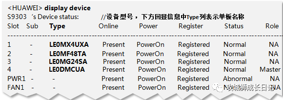
- 任意视图执行命今display device,查看设备型号及部件信息,其中框式设备主要可查看对应单板名称;
- 登录硬件查询工县,查询当前使用的光模块类型是否和对应设备接口匹配以及光模块是否和光纤型号匹配;
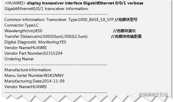
- 两端设备上均在任意视图下执行命令display transceiver interface,检查链路两端光模块参数是否一致;
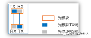
- 检查光纤连线方式是否正确,光模块一般包含发送端(TX)和接收端(RX)。光接口对接时需要两根光纤将一端光模块TX端与另一端RX连接,一端光模块RX端与另一端TX连接;
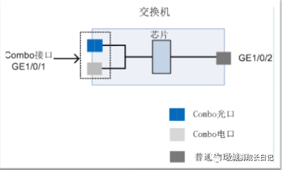
- 判断接口是否为Combo接口,如果是Combo接口,检查接口使用方法是否正确,即接口当前工作模式是否和您当前接口连线是否一致。
如下图所示,Combo接口GE1/0/1在设备面板上对应两个接口: Combo光口和Combo电口。Combo光口和Combo电口不能同时工作。当用户需要对Combo光口或Combo电口进行属性配置时,都只需要进入同一接口视图GE1/0/1进行配置即可
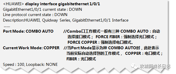
任意视图下执行命令display interface,查看接口是否为Combo接口,以及当前工作模式是否正常.
 图片
图片
(3) 故障恢复方法
根据硬件查询工具,确保当前使用的光模块与光口匹配,光模块与光纤匹配,如果不一致,请更换相应部件。
如果当前接口为Combo接口,则Combo接口工作模式选定原则如下:
- Combo电口没有连接网线,当Combo光口插上光模块时,则Combo接口选择光口模式
- Combo电口已经连接网线,且Combo接口处于UP状态,此时即使Combo光口插上光模块Combo接口仍选择为电口模式。但是设备重启后,Combo接口工作模式将变为光口模式
- Combo电口已经连接网线,目Combo接口处于DOWN状态,此时Combo光口插上光模块Combo接口将选择光口模式。
- 当指定Combo接口工作模式为自动选择模式时(接口视图下执行comboport auto,默认设备Combo接口工作模式为auto ),系统将检测Combo光口是否有光模块插入,进行模式选择:
综上所述,Combo接口工作模式为自动选择模式时,只要Combo光口已插上光模块,则设备重启后,Combo接口都将选择光口模式。
当Combo接口的工作模式设置为强制模式时,需要根据本端与对端设备连接的接口类型进行配置:
- 如果本端Combo电口与对端电口相连,则需要强制指定Combo接口的工作模式为copper,即接视图下执行combo-port copper.
- 如果本端Combo光口与对端光口相连,则需要制指定Combo接口的工作模式为fber,即接视图下执行combo-port fiber.
综上所述,当确定正确的传输介质后(光纤或者网线)后,就可以确定Combo口正确的工作模式您可以直接使用命令combo-port{copper|fiber],强制配置接口工作模式和连接介质保持致即可。
4.环--环境因素导致的故障
(1) 原因描述
交换机使用场景复杂多样,设备可以处于网络中任意一个层级。当交换机及其连接介质由于环境因素导致异常时接口状态也可能物理DOWN
(2) 故障诊断操作步骤
- 检查机房温度及湿度状况:S交换机工作环境温度:0C~45C,对湿度应在5%RH~95%RH之间,不结露
- 检查线缆布放状况:电源线与业务线缆分开布放。不能出现强弱电线缆并行的情况,防止干扰。检查是否有高温或者机架磨损导致网线破损老化的问题
(3) 恢复方法
- 若机房的环境温度长期不能满足要求,应考虑检修或更换机房的空调系统。若机房的相对湿度过大,应考虑为机房安装除湿设备;
- 若机房的相对湿度过小,应考虑为机房安装加湿设备,若出现强弱电线缆并行现象,请重新部署线缆走向,强弱电线缆分离。如因环境因素导致网线损伤老化,请更换网线。