A must-read for newbies to MPLS static configuration! Detailed case explanations help you get started quickly!
2023.10.16

A must-read for newbies to MPLS static configuration! Detailed case explanations help you get started quickly!
Today we will take a look at the basic configuration cases of MPLS and further explore the application of MPLS in practice.

MPLS basic configuration commands
1. Configure LSR ID
[Huawei] mpls lsr-id lsr-idThe mpls lsr-id command is used to configure the LSR ID. The LSR ID is used to uniquely identify an LSR in the network. LSR does not have a default LSR ID and must be configured manually. In order to improve the reliability of the network, it is recommended to use the address of a loopback interface of the LSR as the LSR ID and to uniformly plan the LSR IDs of all LSRs in the network before configuration.
2. Enable MPLS
[Huawei] mplsThe mpls command is used to enable the global MPLS capability of this node and enter the MPLS view.
[Huawei-GigabitEthernet0/0/0] mplsIn interface view, enable the MPLS function of the current interface. You need to enable the global MPLS capability before executing the MPLS enable command on the interface.
Static LSP configuration command
1.Ingress LSR configuration
[Huawei] static-lsp ingress lsp-name destination ip-address { mask-length | mask } { nexthop next-hop-address | outgoing-interface interface-type interface-number } * out-label out-labelThe static-lsp ingress command is used to configure a static LSP for the ingress node.
- It is recommended to configure a static LSP by specifying next-hop to ensure that there is a routing entry that accurately matches the specified destination IP address in the local routing table, including the destination IP address and next-hop IP address. If the LSP outbound interface is of Ethernet type, the nexthop next-hop-address parameter must be configured to ensure normal forwarding of the LSP.
- The value range of out-label is 16~1048575.
2.Transit LSR configuration
[Huawei] static-lsp transit lsp-name [ incoming-interface interface-type interface-number ] in-label in-label { nexthop next-hop-address | outgoing-interface interface-type interface-number }* out-label out-labelThe static-lsp transit command is used to configure a static LSP for the intermediate forwarding node.
- The configuration rules for the next hop and outbound interface are consistent with the Ingress LSR.
- The value range of in-label is 16~1023.
- The value range of out-label is 16~1048575.
3.Egress LSR configuration
[Huawei] static-lsp egress lsp-name [ incoming-interface interface-type interface-number ] in-label in-label The static-lsp egress command is used to configure a static LSP on the egress node.
- The value range of in-label is 16~1023.
4. View static LSP configuration
[Huawei] display mpls static-lsp [ lsp-name ] [ { include | exclude } ip-address mask-length ] [ verbose ]Use the display mpls static-lsp command to view static LSP information.
Static LSP configuration case
1. Case introduction:
The IGP protocol has been deployed between R1, R2 and R3, so the 1.1.1.0/24 and 3.3.3.0/24 networks can communicate with each other. It is now required to configure a static LSP so that the two networks can communicate with each other based on MPLS. The label distribution is as shown in the figure.
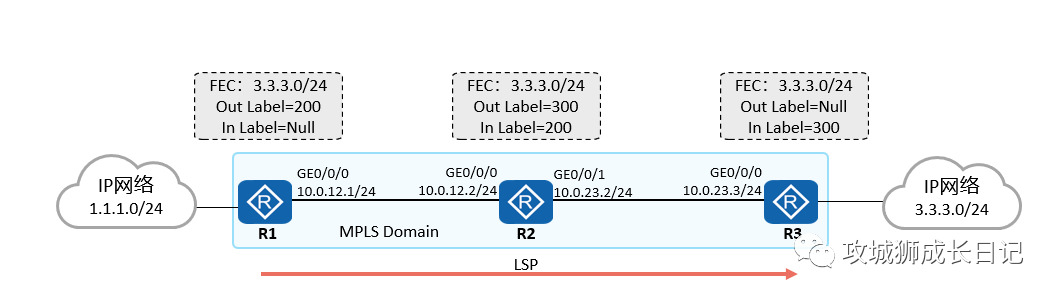
Topology
2. Configuration ideas:
- Enable OSPF dynamic routing protocol on the device
- Enable MPLS function on devices and interfaces
- Configure static LSP as planned
3. Configuration steps:
(1) The LSR IDs of the three routers are 10.1.1.1, 10.1.1.2 and 10.1.1.3 respectively. Taking R1 as an example, enable the MPLS function globally and on the interface.
[R1]mpls lsr-id 10.1.1.1
[R1]mpls
Info: Mpls starting, please wait... OK!
[R1-mpls]quit
[R1]interface GigabitEthernet 0/0/0
[R1-GigabitEthernet0/0/0]mpls
[R1-GigabitEthernet0/0/0]quit]
(2) The OSPF dynamic routing protocol is enabled on all three routers. Take R1 as an example. Others are similar.
[R1] osfp 1 router-id 10.1.1.1
[R1-ospf-1] area 0
[R1-ospf-1-area-0.0.0.0] network 10.1.1.1 0.0.0.0
[R1-ospf-1-area-0.0.0.0] network 10.0.12.0 0.0.0.255
[R1-ospf-1-area-0.0.0.0]quit
(3) Configure a static LSP from R1 to R3.
[R1] static-lsp ingress 1to3 destination 3.3.3.0 24 nexthop 10.0.12.2 out-label 200
[R2] static-lsp transit 1to3 incoming-interface GigabitEthernet 0/0/0 in-label 200 nexthop 10.0.23.3 out-label 300
[R3] static-lsp egress 1to3 incoming-interface GigabitEthernet 0/0/0 in-label 300
4. Check configuration
[R1]display mpls lsp
---------------------------------------------------------------------
                 LSP Information: STATIC LSP
---------------------------------------------------------------------
FEC                  In/Out Label    In/Out IF         Vrf Name
3.3.3.0/24         NULL/200        -/GE0/0/0
[R2]display mpls lsp
---------------------------------------------------------------------
LSP Information: STATIC LSP
---------------------------------------------------------------------
FEC In/Out Label In/Out IF Vrf Name
3.3.3.0/24 200/300 GE0/0/0/GE0/0/1[R3]display mpls lsp
---------------------------------------------------------------------
LSP Information: STATIC LSP
---------------------------------------------------------------------
FEC In/Out Label In/Out IF Vrf Name
3.3.3.0/24 300/NULL GE0/0/0/-After testing, there is no problem in the ping test from the host in the 1.1.1.0/24 network segment to the host 3.3.3.0/24.
5. Packet capture analysis
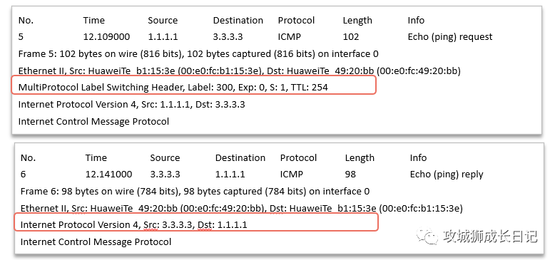
From the packet capture information, it can be seen that the packets from the host in the 1.1.1.0/24 network segment to the host 3.3.3.0/24 are forwarded based on MPLS labels. The packets from the host in the 3.3.3.0/24 network segment to the host 1.1.1.0/24 are forwarded based on the IP header.