Discover VLAN Aggregation: How to Optimize Your Network Performance
2023.10.07

Discover VLAN Aggregation: How to Optimize Your Network Performance
This series mainly introduces several advanced VLAN technologies, including VLAN aggregation, MUX VLAN, and QinQ, to further deepen the understanding and application of advanced VLAN technologies.
VLAN technology is widely used in campus networks. VLANs are usually used to isolate broadcast domains. Each VLAN belongs to a broadcast domain. During network planning, you need to assign a gateway to each broadcast domain. If there are too many VLANs, IP address planning will become more difficult, and a large number of IP addresses may even be wasted. This series mainly introduces several advanced VLAN technologies, including VLAN aggregation, MUX VLAN, and QinQ, to further deepen the understanding and application of advanced VLAN technologies.

background
In general three-layer switches, one VLAN corresponds to one VLANIF interface to achieve intercommunication between broadcast domains, which in some cases leads to a waste of IP addresses. Because in the subnet corresponding to a VLAN, the subnet number, subnet broadcast address, and subnet gateway address cannot be used as the host IP address in the VLAN, and the actual number of hosts connected in the subnet may be less than the number of available IP addresses, idle The IP address will also be wasted because it can no longer be used by other VLANs.
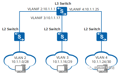
For example, in the VLAN planning shown in the figure above, VLAN2 is expected to need 10 host addresses in the future, but according to the addressing method, it needs to be assigned at least one subnet 10.1.1.0/28 with a mask length of 28, of which 10.1 .1.0 is the subnet number, 10.1.1.15 is the subnet directed broadcast address, and 10.1.1.1 is the subnet default gateway address. These three addresses cannot be used as host addresses. The remaining range is 10.1.1.2~10.1.1.14 of addresses can be used by the host, 13 in total.
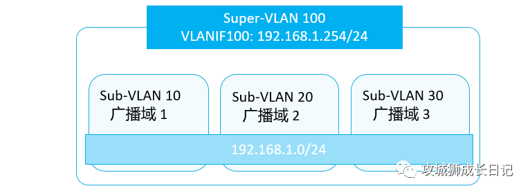
In order to solve the above problems, VLAN aggregation came into being. By introducing the concepts of Super-VLAN and Sub-VLAN, each Sub-VLAN corresponds to a broadcast domain, and associates multiple Sub-VLANs with one Super-VLAN. Only one IP subnet is assigned to the Super-VLAN. Sub-VLAN all use the IP subnet and default gateway of Super-VLAN for Layer 3 communication.
What is VLAN aggregation
VLAN Aggregation (also called Super VLAN) refers to using multiple VLANs (called Sub-VLANs) to isolate broadcast domains within a physical network, and aggregating these Sub-VLANs into a logical VLAN (called Super-VLAN). VLAN), these Sub-VLANs use the same IP subnet and default gateway, thus achieving the purpose of saving IP address resources.
working principle
Compared with every ordinary VLAN, which has a Layer 3 logical interface and several physical interfaces, the Super-VLAN and Sub-VLAN defined by VLAN aggregation are special:
- Sub-VLAN: Contains only physical interfaces and cannot establish Layer 3 VLANIF interfaces. It is used to isolate broadcast domains. The Layer 3 communication between hosts in each Sub-VLAN and the outside is realized by the Layer 3 VLANIF interface of the Super-VLAN.
- Super-VLAN: Only establishes a three-layer VLANIF interface, does not include physical interfaces, and corresponds to the subnet gateway. Different from ordinary VLANs, the Up of its VLANIF interface does not depend on the Up of its own physical interface. Instead, it goes Up as long as there is an Up physical interface in the Sub-VLAN it contains.
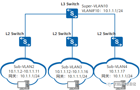
VLAN aggregation implementation diagram
According to the implementation method of VLAN aggregation, let VLAN10 be Super-VLAN, assign subnet 10.1.1.0/24, and VLAN2~VLAN4 as the Sub-VLAN of Super-VLAN10.
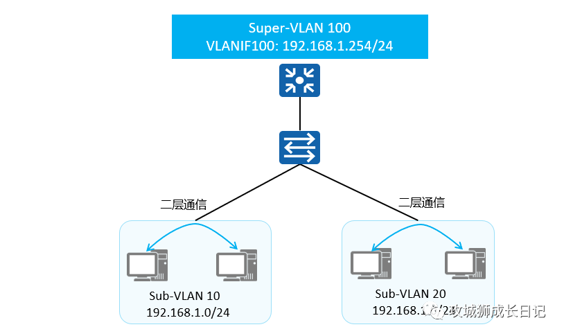
1. Same Sub-VLAN internal communication
The same Sub-VLAN belongs to the same broadcast domain, so the same Sub-VLAN can communicate directly through Layer 2.
2. Examples of communication between different Sub-VLANs
When communicating between different Sub-VLANs, the IP addresses belong to the same network segment, so the host will send an ARP request. However, different Sub-VLANs actually belong to different broadcast domains, so ARP messages cannot be delivered to other Sub-VLANs. ARP The request does not receive a response, and the device cannot learn the peer MAC address, thus failing to complete communication between Sub-VLANs. To achieve communication between Sub-VLANs, the ARP proxy function needs to be enabled in the VLANIF of the Super-VLAN.
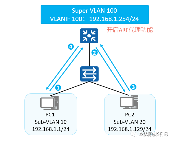
After Super-VLAN VLANIF100 turns on ARP proxy, the communication process between PC1 and PC2 is as follows:
- PC1 finds that PC2 is on the same network segment as itself, and that its ARP table does not have a corresponding entry for PC2, so it directly sends an ARP broadcast to request PC2's MAC address.
- VLANIF 100 corresponding to the Super-VLAN serving as the gateway receives the ARP request from PC1. Since the inter-Sub-VLAN ARP proxy function is enabled on the gateway, an ARP broadcast is sent to all Sub-VLAN interfaces of Super-VLAN 100, requesting PC2 MAC address.
- After receiving the ARP broadcast sent by the gateway, PC2 responds to the request with ARP.
- After the gateway receives the response from PC2, it responds with its MAC address to PC1. The messages that PC1 wants to send to PC2 are sent to the gateway first, and the gateway performs Layer 3 forwarding.
3.Layer 2 communication between Sub-VLAN and other devices
When Sub-VLAN communicates with other devices at Layer 2, it is no different from ordinary Layer 2 communication within a VLAN.
Since Super-VLAN does not belong to any physical interface, any packets carrying Super-VLAN tags will not be processed.
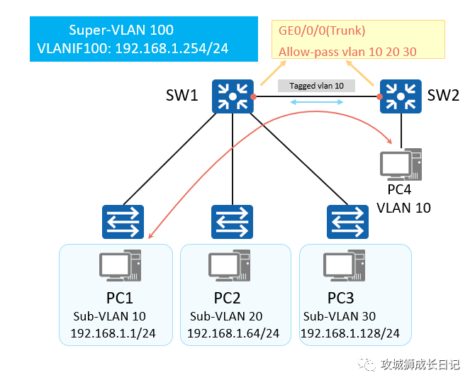
Example of Sub-VLAN Layer 2 communication process:
- Packets entering SW1 from PC1 will be tagged with VLAN10. In SW1, this Tag will not become the Tag of VLAN100 because VLAN10 is a Sub-VLAN of VLAN100.
- When the packet goes out from GE0/0/0 of SW1, it still carries the tag of VLAN10. In other words, SW1 itself will not send VLAN100 packets. Even if other devices send VLAN100 packets to this device, these packets will be discarded because there is no corresponding physical interface for VLAN100 on SW1.
- For other devices, the only valid VLANs are Sub-VLAN 10, 20 and 30, and all packets are exchanged in these VLANs. Therefore, although VLAN aggregation is configured on SW1, the Layer 2 communication with other devices does not involve Super-VLAN and is the same as the normal Layer 2 communication process.
When a PC in the Sub-VLAN needs to communicate with other networks at Layer 3, the data is first sent to the default gateway, which is the VLANIF corresponding to the Super-VLAN, and then routed.
VLAN aggregation application scenarios
As shown in the figure below, a company has multiple departments. In order to improve business security, different departments are divided into different VLANs. Each department needs to access the Internet, and due to business needs, Department 1 and Department 2 need to communicate, and Department 3 and Department 4 need to communicate with each other, but the company's IP address is limited.
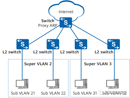
The company's needs can be met by deploying VLAN aggregation. Super VLAN 2 and Super VLAN 3 are deployed on the Switch, Sub VLAN 21 and Sub VLAN 22 are aggregated into Super VLAN 2, and Sub VLAN 31 and Sub VLAN 32 are aggregated into Super VLAN 3. middle. In this way, you only need to assign IP addresses to Super VLAN 2 and Super VLAN 3 on the Switch. Users in departments 1 and 2 can access the Internet through the IP address of Super VLAN 2, and users in departments 3 and 4 can access the Internet through the IP address of Super VLAN 3. Accessing the Internet by IP address not only meets the needs of various departments to access the Internet, but also saves IP address resources. At the same time, configure Proxy ARP on Super VLAN 2 and Super VLAN 3 of the Switch respectively to achieve intercommunication between departments 1 and 2, and between departments 3 and 4.
VLAN aggregation key configuration commands
(1) Create Super-VLAN:
[Huawei-vlan100] aggregate-vlan- Super-VLAN cannot contain any physical interfaces, and VLAN1 cannot be configured as Super-VLAN.
- The VLAN ID in Super-VLAN and the VLAN ID in Sub-VLAN must use different VLAN IDs.
(2) Add Sub-VLAN to Super-VLAN
[Huawei-vlan100] access-vlan { vlan-id1 [ to vlan-id2 ] }[Huawei-vlan100] access-vlan { vlan-id1 [ to vlan-id2 ] }When adding a Sub-VLAN to a Super-VLAN, you must ensure that the Sub-VLAN does not create a corresponding VLANIF interface.
(3) (Optional) Enable Proxy ARP on the VLANIF interface corresponding to Super-VLAN
[Huawei-vlanif100] arp-proxy inter-sub-vlan-proxy enableEnable the Proxy ARP function between Sub-VLANs.
Configuration example
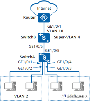
Configuring VLAN aggregation networking diagram
A company has multiple departments located on the same network segment. In order to improve business security, users in different departments are divided into different VLANs. As shown in the figure above, VLAN2 and VLAN3 belong to different departments. All departments have requirements for accessing the Internet. At the same time, due to business needs, users in different departments need to communicate with each other.
1. Configuration ideas
VLAN aggregation can be deployed on SwitchB to aggregate VLANs from different departments into Super VLANs. In this way, users in different departments can access the Internet through Super VLANs. At the same time, in order to allow users between departments to communicate, the Proxy ARP function is deployed on the Super VLAN. Use the following ideas to configure VLAN aggregation:
- Configure VLANs and interfaces on SwitchA and SwitchB, divide users from different departments into different VLANs, and transparently transmit each VLAN to SwitchB.
- Configure Super-VLAN and its corresponding VLANIF interface and uplink route on SwitchB so that users in different departments can access the Internet.
- Enable the Proxy ARP function of Super-VLAN on SwitchB to enable Layer 3 intercommunication between users in different departments.
2. Operation steps
(1) Basic configuration will not be described in detail. Given is the key configuration
(2) Configure Super-VLAN 4 on SwitchB, and add VLAN2 and VLAN3 to Super-VLAN 4 as its Sub-VLAN.
[SwitchB] vlan 4
[SwitchB-vlan4] aggregate-vlan
[SwitchB-vlan4] access-vlan 2 to 3
[SwitchB-vlan4] quit
(3) Create and configure VLANIF4 so that users in different departments can access the Internet through Super-VLAN 4.
[SwitchB] interface vlanif 4
[SwitchB-Vlanif4] ip address 10.1.1.1 255.255.255.0
[SwitchB-Vlanif4] quit
(4) Configure a default static route to the egress gateway Router on SwitchB so that users can access the Internet.
[SwitchB] ip route-static 0.0.0.0 0.0.0.0 10.10.1.2(5) Configure Proxy ARP under Super-VLAN 4 of SwitchB to enable Layer 3 interoperability between users in different departments.
[SwitchB] interface vlanif 4
[SwitchB-Vlanif4] arp-proxy inter-sub-vlan-proxy enable
[SwitchB-Vlanif4] quit