Master port isolation technology to make the network more secure

Master port isolation technology to make the network more secure
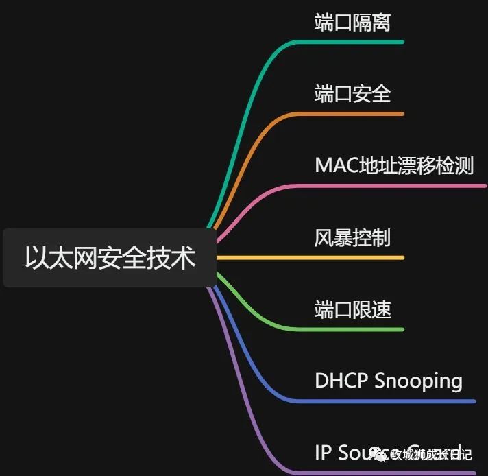
At present, Ethernet technology is widely used in networks. However, the existence of various network attacks (such as attacks on ARP, DHCP and other protocols) not only prevents legitimate network users from accessing network resources normally, but also poses a serious threat to network information security. Therefore, the security of Ethernet switching is becoming increasingly important. The more important it is.
This series introduces common Ethernet switching security technologies, including port isolation, port security, MAC address drift detection, storm control, port speed limit, MAC address table security, DHCP Snooping and IP Source Guard, etc., to improve the understanding of Ethernet switching. Understanding and awareness of network switching security.
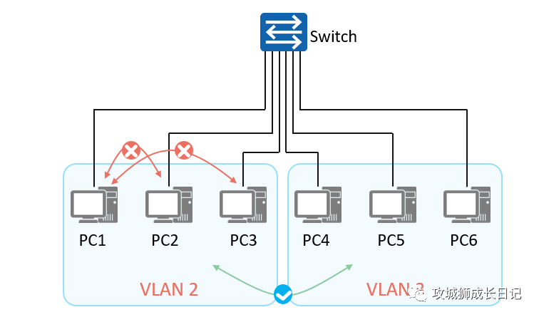
- In order to achieve Layer 2 isolation between packets in an Ethernet switching network, users usually add different ports to different VLANs to achieve Layer 2 broadcast domain isolation.
- In large-scale networks, there are many types of business requirements. Implementing Layer 2 isolation of packets only through VLAN will waste limited VLAN resources.
As shown in the figure below, due to certain business requirements, although PC1 and PC2 belong to the same VLAN, they are required to not be able to communicate at Layer 2 (but Layer 3 is allowed to communicate with each other). PC1 and PC3 cannot communicate with each other under any circumstances, but VLAN 3 Hosts in VLAN 2 can access hosts in VLAN 2. So how to solve this problem?
Overview of port isolation technology
The port isolation function can be used to isolate ports within the same VLAN. Users only need to add ports to the isolation group to realize Layer 2 data isolation between ports in the isolation group. The port isolation function provides users with a safer and more flexible networking solution.
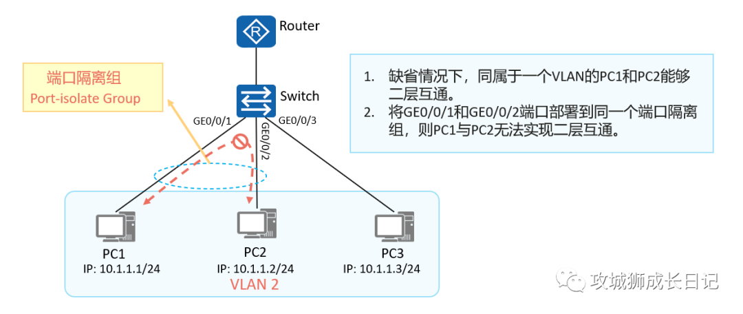
Principle of port isolation technology
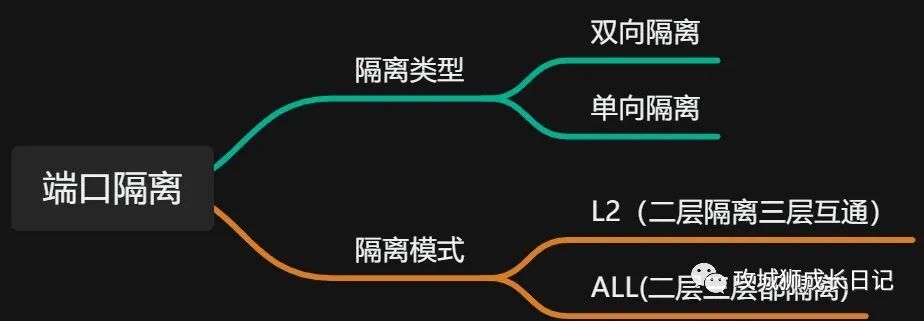
(1) Two-way isolation
Interfaces in the same port isolation group are isolated from each other, but interfaces in different port isolation groups are not isolated from each other. Port isolation only applies to port isolation group members on the same device. This function cannot be implemented for interfaces on different devices.
(2) One-way isolation
To achieve isolation between interfaces in different port isolation groups, you can configure unidirectional isolation between interfaces. By default, port unidirectional isolation is not configured.
(3) L2 (Layer 2 isolation and Layer 3 interoperability)
Isolate broadcast packets within the same VLAN, but users on different ports can still communicate at Layer 3. By default, the port isolation mode is Layer 2 isolation and Layer 3 interworking.
(4) ALL (the second and third floors are isolated)
Users on different ports in the same VLAN are completely isolated at Layer 2 and Layer 3 and cannot communicate.
When using the isolation mode of Layer 2 isolation and Layer 3 interworking, enable the intra-VLAN Proxy ARP function on the VLANIF interface and configure arp-proxy inner-sub-vlan-proxy enable to achieve communication between hosts in the same VLAN.
Port isolation configuration command
(1) Enable port isolation function
[Huawei-GigabitEthernet0/0/1] port-isolate enable [ group group-id ]- 1.
By default, the port isolation function is not enabled. If the group-id parameter is not specified, the default port isolation group added is 1.
(2) (Optional) Configure port isolation mode
Huawei] port-isolate mode { l2 | all }- 1.
By default, the port isolation mode is L2.
- The L2 port isolation mode is Layer 2 isolation and Layer 3 interworking.
- The port isolation mode of all is isolation of both Layer 2 and Layer 3.
(3) Configure port one-way isolation
[Huawei-GigabitEthernet0/0/1] am isolate {interface-type interface-number }&<1-8>- 1.
The am isolate command is used to configure one-way isolation between the current interface and the specified interface. After configuring one-way isolation between interface A and interface B, packets sent from interface A cannot reach interface B, but packets sent from interface B can reach interface A. By default, port unidirectional isolation is not configured.
Port isolation configuration example
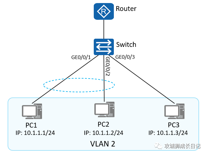
As shown in the figure: PC1, PC2 and PC3 belong to VLAN 2. By configuring port isolation, PC3 can communicate with PC1 and PC2, but PC1 and PC2 cannot communicate with each other.
Switch configuration is as follows:
[Switch] vlan 2
[Switch] port-isolate mode all
[Switch] interface GigabitEthernet 0/0/1
[Switch-GigabitEthernet0/0/1] port link-type access
[Switch-GigabitEthernet0/0/1] port default vlan 2
[Switch-GigabitEthernet0/0/1] port-isolate enable group 2
[Switch] interface GigabitEthernet 0/0/2
[Switch-GigabitEthernet0/0/2] port link-type access
[Switch-GigabitEthernet0/0/2] port default vlan 2
[Switch-GigabitEthernet0/0/2] port-isolate enable group 2
[Switch] interface GigabitEthernet 0/0/3
[Switch-GigabitEthernet0/0/3] port link-type access
[Switch-GigabitEthernet0/0/3] port default vlan 2- 1.
- 2.
- 3.
- 4.
- 5.
- 6.
- 7.
- 8.
- 9.
- 10.
- 11.
- 12.
- 13.
- display port-isolate group { group-id | all } to view the configuration of the port isolation group.
- The clear configuration port-isolate command clears all port isolation configurations on the device with one click.
- The port-isolate exclude vlan command configures the VLANs excluded when the port isolation function takes effect.
Port isolation configuration verification
(1) Check the ports in the port isolation group through display port-isolate group group-number
[SW]display port-isolate group 2
  The ports in isolate group 2:
GigabitEthernet0/0/1 GigabitEthernet0/0/2- 1.
- 2.
- 3.
(2) Verify that the host networks in the same port isolation group cannot communicate with each other.