How to communicate between LAN and Kubernetes internal network
2023.09.11

How to communicate between LAN and Kubernetes internal network
This article mainly talks about the basic knowledge of K8S network and how to connect the LAN and K8S network. I hope it will be helpful to you.
After K8S was built, I encountered a problem. How to debug remotely (don’t debug remotely in the production environment)? Then you need to open up the LAN and K8S internal network. This article mainly introduces how to connect Pod communication, K8S network plug-in, LAN and K8S network.

1. Problem description
During our actual use of K8S, the following requirements emerged:
- When a problem occurs, I want to perform remote debugging.
- After the development of a certain microservice module is completed on the computer, it is hoped that after being started locally, it can be registered in the registration center of the development environment for debugging, instead of starting a bunch of dependent services locally.
The above problems will be very uncomfortable if the office network and the K8S Pod network are not connected.
Since the Kubernetes cluster uses the CNI plug-in to create the Pod/Service internal subnet, the internal IP and domain name are generally inaccessible from the outside, which brings a lot of trouble to development, testing, and joint debugging. Therefore, the development and testing environment Kubernetes cluster internal subnet and Implementing interconnection and interoperability in office LANs is a common problem.
Before getting through, let’s first understand the basic knowledge of K8S network. The network architecture of K8S is relatively complex. Kubernetes itself is not responsible for network communication, but it provides the container network interface CNI (Container Network Interface). The specific network communication is implemented by the CNI plug-in.
This is a standard design to make it easier for users to configure container networks when creating or destroying containers. Users only need to use the CNI plug-in to easily manage the K8S network. There are currently many mainstream open source CNI plug-ins, such as Flannel, Calico, etc.
2. Common terms
Before exploring the CNI plug-in, understand a few terms:
- eth0: It is the name of the fiber optic Ethernet interface card of the system. It may also have other names, such as ens192.
- veth virtual network device: veth devices appear in pairs, with one end connected to the Pod and the other end connected to the CNI.
- netns: netns is the abbreviation of Linux Network Namespace. It is a native network isolation functional component provided by Linux. It can virtualize multiple network spaces in the Linux system to achieve isolation of network resources.
- Layer 2 network: The "data link" layer of the OSI (Open Systems Interconnections) network model. Layer 2 networks handle frame delivery between two adjacent nodes on the network. A notable example of a Layer 2 network is Ethernet, where MAC is represented as a sublayer.
- Layer 3 Network: The "network" layer of the OSI network model. The main focus of Layer 3 networking is routing packets between hosts above Layer 2 connections. IPv4, IPv6, and ICMP are examples of layer 3 network protocols.
- VXLAN: Stands for "Virtual Extensible LAN". First, VXLAN is used to help enable large cloud deployments by encapsulating Layer 2 Ethernet frames in UDP datagrams. VXLAN virtualization is similar to VLAN but offers greater flexibility and functionality (VLAN is limited to 4096 network IDs). VXLAN is an encapsulation and overlay protocol that operates over existing networks.
- Overlay network: Overlay network is a virtual logical network built on the existing network. Overlay networks are often used to provide useful abstractions on top of existing networks and to separate and protect different logical networks.
- Encapsulation: Encapsulation is the process of encapsulating network packets in additional layers to provide additional context and information. In an overlay network, encapsulation is used to translate from the virtual network into the underlying address space so that it can be routed to different locations (packets can be decapsulated and continued to their destination).
- Mesh network: A mesh network is a network in which each node is connected to many other nodes to coordinate routing and achieve greater connectivity. Mesh networking allows routing through multiple paths, providing a more reliable network. The disadvantage of a mesh grid is that each additional node adds significant overhead.
- BGP: Stands for "Border Gateway Protocol" and manages how packets are routed between edge routers. BGP helps figure out how to send packets from one network to another by taking into account available paths, routing rules, and specific network policies. BGP is sometimes used as a routing mechanism in CNI plugins rather than encapsulated overlay networks.
- IP tunneling technology: It is a process in which a router encapsulates a network layer protocol into another protocol for transmission across the network to another router. IP tunneling is a technology that encapsulates an IP packet in another IP packet. This allows a data packet destined for one IP address to be encapsulated and forwarded to another IP address. IP tunnel technology is also called IP encapsulation technology.
3. Pod communication
Before opening up the LAN and Kubernetes internal network, let’s briefly describe how K8S Pods communicate with each other.
1. Pod communication in the same node
Pod communicates with the outside through a virtual Ethernet interface pair (Veth Pair). Veth Pair is like a network cable, with one end inside the Pod and the other end outside the Pod. Pods on the same node communicate through the Linux Bridge, as shown in the figure below.
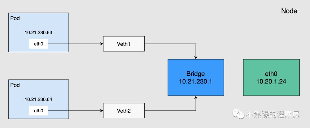
Pods on the same node will connect one end to the bridge through the Veth device, and their IP addresses are dynamically obtained through the bridge and belong to the same network segment as the bridge IP. In addition, the default route of all Pods on the same node points to the bridge, and the bridge is responsible for forwarding all traffic with non-local addresses. Therefore, Pods on the same node can communicate directly.
2. Pod communication between different nodes
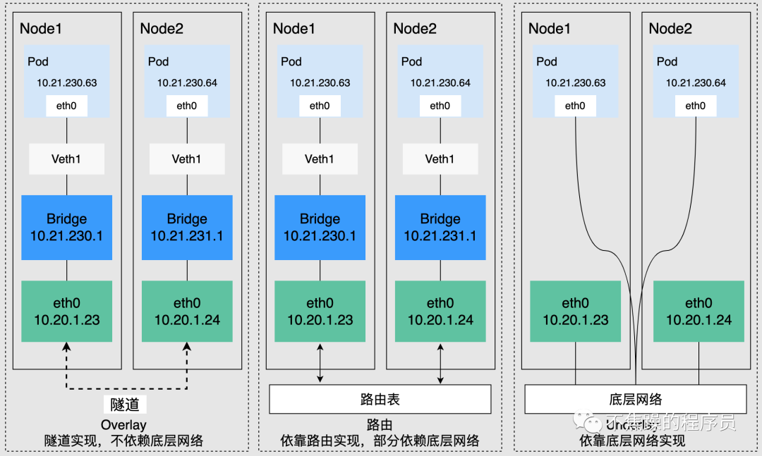
Kubernetes requires that the address of the cluster Pod be unique, so each node in the cluster will be assigned a subnet to ensure that the IP address of the Pod is not repeated within the entire cluster. Pods running on different nodes access each other through IP addresses. This process needs to be implemented through the cluster network plug-in. According to the underlying dependencies, it can be roughly divided into three categories: Overlay mode, routing mode, and Underlay mode.
- Overlay mode is an independent network built through tunnel encapsulation based on the node network, and has its own independent IP address space, switching or routing implementation. The VXLAN protocol is currently one of the most popular overlay network tunnel protocols.
- The routing mode uses the VPC routing table to combine with the underlying network, which can connect containers and hosts more conveniently, and is superior to Overlay's tunnel encapsulation in performance.
- Underlay mode is a network construction technology that uses drivers to directly expose the underlying network interface of a node to the container. It enjoys higher performance. Common solutions include IP VLAN, etc.
4. Network plug-ins
This article only introduces Calico, because I have never used Flannel. K8S network plug-ins on the cloud are basically implemented by cloud vendors in conjunction with their own VPC networks, and are beyond the scope of the introduction.
The k8s network plug-in is mainly divided into: underlay and overlay. Calico is mainly divided into three modes: BGP, IPIP, and VXLAN. BGP belongs to the underlay, and IPIP and VXLAN belong to the overlay.
Calico is an open source network and network security solution for containers, virtual machines, and native host-based workloads. Calico supports a wide range of platforms, including Kubernetes, Docker, OpenStack and bare metal services. The Calico backend supports multiple network modes.
This article mainly analyzes the ipip mode of calico, aiming to understand the calixxxx, tunl0 and other devices generated in the IPIP network mode as well as the cross-node network communication method. The main principle of the ipip mode is to encapsulate a layer of node ip based on the pod ip, so that it can be forwarded to the corresponding destination through the corresponding routing rules.
1. A first look at the Internet
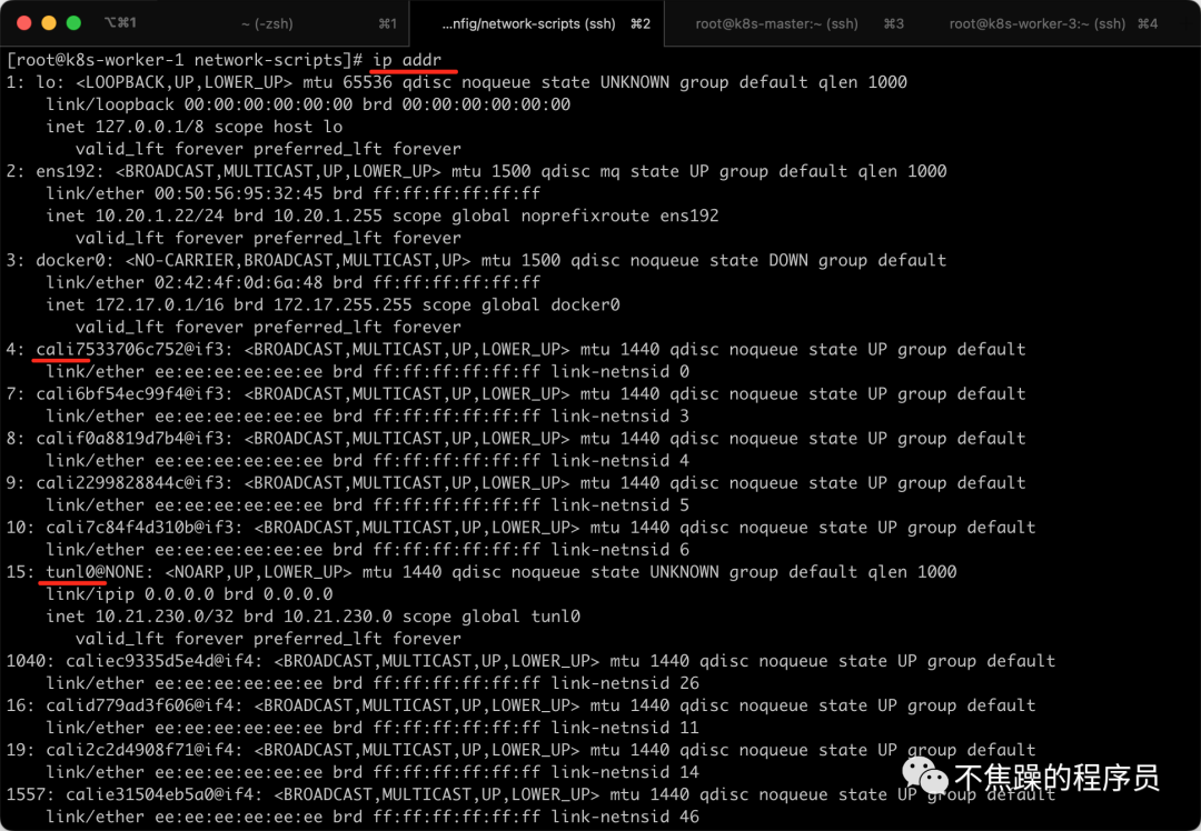
I use the CNI plug-in Calico. For example, through the ip addr command, you can see that there are many virtual network cards starting with cali under the K8S Node node. At the same time, there are also IP tunnels such as tunl0. You can see that the IPIP mode of Calico is used.
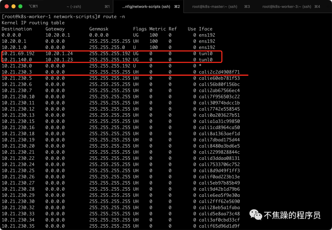
You can also see through the route -n command that each pod corresponds to a virtual network card, and access to other network segments is sent through the tunl0 tunnel.
2.Calico’s IPIP mode:
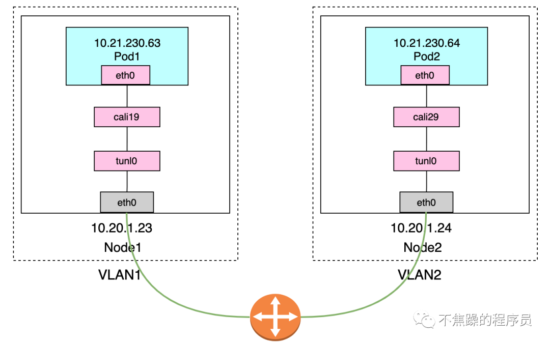
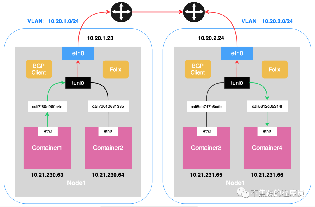
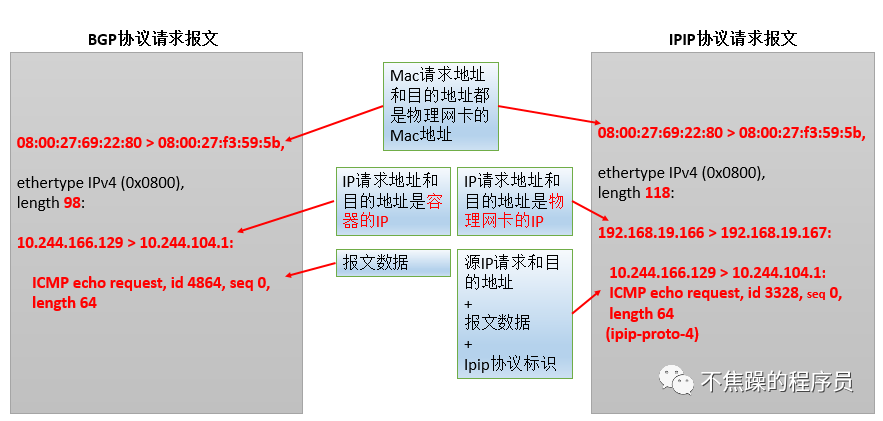
IPIP mode: Calico uses this method by default. Encapsulate a new IP packet in the original IP packet, and modify both the source address IP and the destination IP address in the new IP packet to the peer host IP. When enabled, a tunnel is made between Node routers and the two networks are connected. A virtual network interface named tunl0 will be created on each Node node.
The communication process in IP mode is shown in the following two figures:
Executing ip addr on K8S-Node can see the following information, which includes tunl0 and calixxxxxx:
# 回环地址
1: lo: <LOOPBACK,UP,LOWER_UP> mtu 65536 qdisc noqueue state UNKNOWN group default qlen 1000
    link/loopback 00:00:00:00:00:00 brd 00:00:00:00:00:00
    inet 127.0.0.1/8 scope host lo
       valid_lft forever preferred_lft forever
# 物理网卡
2: ens192: <BROADCAST,MULTICAST,UP,LOWER_UP> mtu 1500 qdisc mq state UP group default qlen 1000
    link/ether 00:50:56:95:32:45 brd ff:ff:ff:ff:ff:ff
    inet 10.20.1.22/24 brd 10.20.1.255 scope global noprefixroute ens192
       valid_lft forever preferred_lft forever
# Docker0
3: docker0: <NO-CARRIER,BROADCAST,MULTICAST,UP> mtu 1500 qdisc noqueue state DOWN group default
    link/ether 02:42:4f:0d:6a:48 brd ff:ff:ff:ff:ff:ff
    inet 172.17.0.1/16 brd 172.17.255.255 scope global docker0
       valid_lft forever preferred_lft forever
# cali打头的Calico网卡
4: cali7533706c752@if3: <BROADCAST,MULTICAST,UP,LOWER_UP> mtu 1440 qdisc noqueue state UP group default
    link/ether ee:ee:ee:ee:ee:ee brd ff:ff:ff:ff:ff:ff link-netnsid 0
7: cali6bf54ec99f4@if3: <BROADCAST,MULTICAST,UP,LOWER_UP> mtu 1440 qdisc noqueue state UP group default
    link/ether ee:ee:ee:ee:ee:ee brd ff:ff:ff:ff:ff:ff link-netnsid 3
8: calif0a8819d7b4@if3: <BROADCAST,MULTICAST,UP,LOWER_UP> mtu 1440 qdisc noqueue state UP group default
    link/ether ee:ee:ee:ee:ee:ee brd ff:ff:ff:ff:ff:ff link-netnsid 4
9: cali2299828844c@if3: <BROADCAST,MULTICAST,UP,LOWER_UP> mtu 1440 qdisc noqueue state UP group default
    link/ether ee:ee:ee:ee:ee:ee brd ff:ff:ff:ff:ff:ff link-netnsid 5
10: cali7c84f4d310b@if3: <BROADCAST,MULTICAST,UP,LOWER_UP> mtu 1440 qdisc noqueue state UP group default
    link/ether ee:ee:ee:ee:ee:ee brd ff:ff:ff:ff:ff:ff link-netnsid 6
# Calico IP隧道使用的Tunl0网卡
15: tunl0@NONE: <NOARP,UP,LOWER_UP> mtu 1440 qdisc noqueue state UNKNOWN group default qlen 1000
    link/ipip 0.0.0.0 brd 0.0.0.0
    inet 10.21.230.0/32 brd 10.21.230.0 scope global tunl0
valid_lft forever preferred_lft forever- 1.
- 2.
- 3.
- 4.
- 5.
- 6.
- 7.
- 8.
- 9.
- 10.
- 11.
- 12.
- 13.
- 14.
- 15.
- 16.
- 17.
- 18.
- 19.
- 20.
- 21.
- 22.
- 23.
- 24.
- 25.
- 26.
- 27.
- 28.
- 29.
- 30.
- 31.
We can also see that veth appears in pairs. For example, enter the Pod, check the network situation, and execute the command kubectl exec -it ingress-nginx-controller-nginx-d864d97df-22ljk -n ingress-nginx -- ip on K8S-Master. addr, you can see the virtual network card number if19, as follows:
# 回环网卡
1: lo: <LOOPBACK,UP,LOWER_UP> mtu 65536 qdisc noqueue state UNKNOWN qlen 1000
    link/loopback 00:00:00:00:00:00 brd 00:00:00:00:00:00
    inet 127.0.0.1/8 scope host lo
       valid_lft forever preferred_lft forever
# 虚拟网卡
3: eth0@if19: <BROADCAST,MULTICAST,UP,LOWER_UP,M-DOWN> mtu 1440 qdisc noqueue state UP
    link/ether 66:e5:5b:b6:77:9a brd ff:ff:ff:ff:ff:ff
    inet 10.21.69.212/32 scope global eth0
       valid_lft forever preferred_lft forever
# 隧道网卡
4: tunl0@NONE: <NOARP> mtu 1480 qdisc noop state DOWN qlen 1000
link/ipip 0.0.0.0 brd 0.0.0.0- 1.
- 2.
- 3.
- 4.
- 5.
- 6.
- 7.
- 8.
- 9.
- 10.
- 11.
- 12.
- 13.
After executing the command ip addr on the K8S-Node where the Pod is located, you can see that there is a cailixxxx numbered 19, as follows:
1: lo: <LOOPBACK,UP,LOWER_UP> mtu 65536 qdisc noqueue state UNKNOWN group default qlen 1000
    link/loopback 00:00:00:00:00:00 brd 00:00:00:00:00:00
    inet 127.0.0.1/8 scope host lo
       valid_lft forever preferred_lft forever
2: ens192: <BROADCAST,MULTICAST,UP,LOWER_UP> mtu 1500 qdisc mq state UP group default qlen 1000
    link/ether 00:50:56:95:c0:f4 brd ff:ff:ff:ff:ff:ff
    inet 10.20.1.24/24 brd 10.20.1.255 scope global noprefixroute ens192
       valid_lft forever preferred_lft forever
3: docker0: <NO-CARRIER,BROADCAST,MULTICAST,UP> mtu 1500 qdisc noqueue state DOWN group default
    link/ether 02:42:2c:ea:87:52 brd ff:ff:ff:ff:ff:ff
    inet 172.17.0.1/16 brd 172.17.255.255 scope global docker0
       valid_lft forever preferred_lft forever
5: cali7359ae97a07@if3: <BROADCAST,MULTICAST,UP,LOWER_UP> mtu 1440 qdisc noqueue state UP group default
    link/ether ee:ee:ee:ee:ee:ee brd ff:ff:ff:ff:ff:ff link-netnsid 1
6: cali763ea01ddd0@if3: <BROADCAST,MULTICAST,UP,LOWER_UP> mtu 1440 qdisc noqueue state UP group default
    link/ether ee:ee:ee:ee:ee:ee brd ff:ff:ff:ff:ff:ff link-netnsid 2
8: cali0140629a81f@if3: <BROADCAST,MULTICAST,UP,LOWER_UP> mtu 1440 qdisc noqueue state UP group default
    link/ether ee:ee:ee:ee:ee:ee brd ff:ff:ff:ff:ff:ff link-netnsid 4
10: calid3a5006f559@if3: <BROADCAST,MULTICAST,UP,LOWER_UP> mtu 1440 qdisc noqueue state UP group default
    link/ether ee:ee:ee:ee:ee:ee brd ff:ff:ff:ff:ff:ff link-netnsid 6
11: calic2abb800440@if3: <BROADCAST,MULTICAST,UP,LOWER_UP> mtu 1440 qdisc noqueue state UP group default
    link/ether ee:ee:ee:ee:ee:ee brd ff:ff:ff:ff:ff:ff link-netnsid 7
12: cali06eecb511af@if3: <BROADCAST,MULTICAST,UP,LOWER_UP> mtu 1440 qdisc noqueue state UP group default
    link/ether ee:ee:ee:ee:ee:ee brd ff:ff:ff:ff:ff:ff link-netnsid 8
13: cali26321116fa3@if3: <BROADCAST,MULTICAST,UP,LOWER_UP> mtu 1440 qdisc noqueue state UP group default
    link/ether ee:ee:ee:ee:ee:ee brd ff:ff:ff:ff:ff:ff link-netnsid 9
17: calia5d32a88758@if3: <BROADCAST,MULTICAST,UP,LOWER_UP> mtu 1440 qdisc noqueue state UP group default
    link/ether ee:ee:ee:ee:ee:ee brd ff:ff:ff:ff:ff:ff link-netnsid 13
# Pod内的eht0标记的是19号和这里的19号是配对的
19: calib51fc1cd61e@if3: <BROADCAST,MULTICAST,UP,LOWER_UP> mtu 1440 qdisc noqueue state UP group default
    link/ether ee:ee:ee:ee:ee:ee brd ff:ff:ff:ff:ff:ff link-netnsid 15
20: cali5910af186a4@if3: <BROADCAST,MULTICAST,UP,LOWER_UP> mtu 1440 qdisc noqueue state UP group default
    link/ether ee:ee:ee:ee:ee:ee brd ff:ff:ff:ff:ff:ff link-netnsid 16
21: calie8b8d191185@if3: <BROADCAST,MULTICAST,UP,LOWER_UP> mtu 1440 qdisc noqueue state UP group default
link/ether ee:ee:ee:ee:ee:ee brd ff:ff:ff:ff:ff:ff link-netnsid 17- 1.
- 2.
- 3.
- 4.
- 5.
- 6.
- 7.
- 8.
- 9.
- 10.
- 11.
- 12.
- 13.
- 14.
- 15.
- 16.
- 17.
- 18.
- 19.
- 20.
- 21.
- 22.
- 23.
- 24.
- 25.
- 26.
- 27.
- 28.
- 29.
- 30.
- 31.
- 32.
- 33.
- 34.
- 35.
3.Calico’s BGP mode:
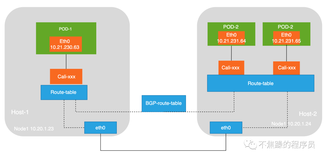
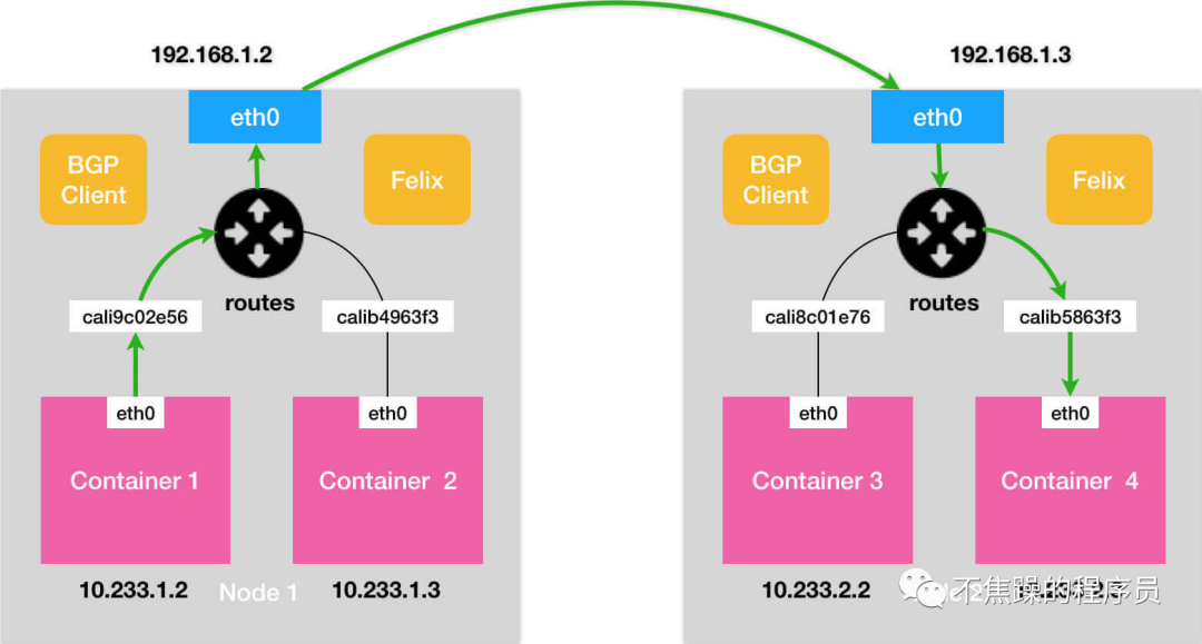
BGP mode: Use nodes as virtual routers to achieve network access between containers in the cluster through the BGP routing protocol. No additional tunnels are created. It will be installed on all node hosts in daemonset mode. Each host starts a bird (BGP client). It will inform the hosts in the cluster of the IP segments allocated by all nodes in the calico network, and pass the network card of the default gateway of the machine. (For example: eth0) The biggest difference between the BGP network and the IPIP network for forwarding data is that there is no tunnel device tunl0. As introduced earlier, the traffic between pods in the IPIP network is sent to tunl0, and then tunl0 sends it to the peer device. In the BGP network, traffic between pods is directly sent to the destination from the network card, reducing the tunl0 link.
The communication process in BGP mode is shown in the figure below:
- Advantages of BGP mode: less packetization and unpacking process, higher performance.
- Disadvantages of BGP mode: More routing rules need to be maintained.
- Advantages of IPIP tunnel mode: simple, because most of the work is implemented by the Linux kernel module, and the workload at the application level is less.
- Disadvantages of IPIP tunnel mode: The main problem is low performance because of the need to packetize and receive packets.
5. Intercommunication between LAN and Kubernetes internal network
If the K8S cluster is deployed in the LAN or in its own data center, and the gateways on the entire link can be configured, using a static routing table is the simplest way. The principle is to act on the third network layer of the network model. Directly tell the gateway to whom certain IPs should be sent.
Through the above K8S network knowledge and the screenshot of route forwarding seen by executing the command, we know that K8S-Node is actually a virtual route. As long as the request is forwarded to K8S-Node, then the Pod can be accessed.
To give the simplest example, K8S in a certain development environment is deployed on the same LAN as the office. There are two lines below to connect to the network, as shown below:
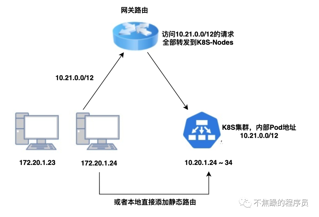
At this time, the company's operation and maintenance only needs to add static routing rules on the gateway router and transfer all IP packets belonging to the Pod/Service CIDR of K8S to one of the K8S nodes. In this way, when accessing an IP such as 10.96.0.1, the network packet will arrive A certain cluster physical node, and the physical node or VM in the cluster, generally the K8S network plug-in (CNI) will communicate with the Pod/Service CIDR.
If the machine deployed by K8S is not under the same gateway as the company office, or is deployed in a self-built data center, the entire link will have several more gateways. Each gateway on the link needs to configure a routing table to route the corresponding CIDR to the adjacent If it is an office network to reach the K8S cluster on the cloud, it only needs to go from the router to the cloud through VPN, as shown below:
