Interpretation of Overlay Network Technology

Interpretation of Overlay Network Technology
Introduction
In the traditional historical stage, the network of the data center is based on the three-tier architecture (core, aggregation, and access) as the basic standard. In the process of specific implementation, with the continuous development of technology, different manufacturers have different construction methods. Some manufacturers add virtualization technology to the core layer to realize the virtualization separation of the core layer and the aggregation layer on the physical device, making the The overall network architecture tends to be flat; some manufacturers add virtualization technology to the aggregation layer and access layer to realize the virtualization separation of the aggregation layer and the access layer on physical devices. But no matter how it is changed, it does not change the basic principles of Ethernet network transmission. It is necessary to rely on network addresses and physical addresses for control and forwarding. However, with the development of cloud computing, the scale of data centers is mostly moving towards large-scale and ultra-flexible needs. Then there are the following problems such as the difficulty of cross-region migration and protection of virtual computing, the limited scale of cluster network isolation, and the limited overall network resources of the data center. It is against this historical background that the Overlay network, represented by vxlan, debuted.
1. What is an Overlay Network?
1.1 The basic structure of the overlay network
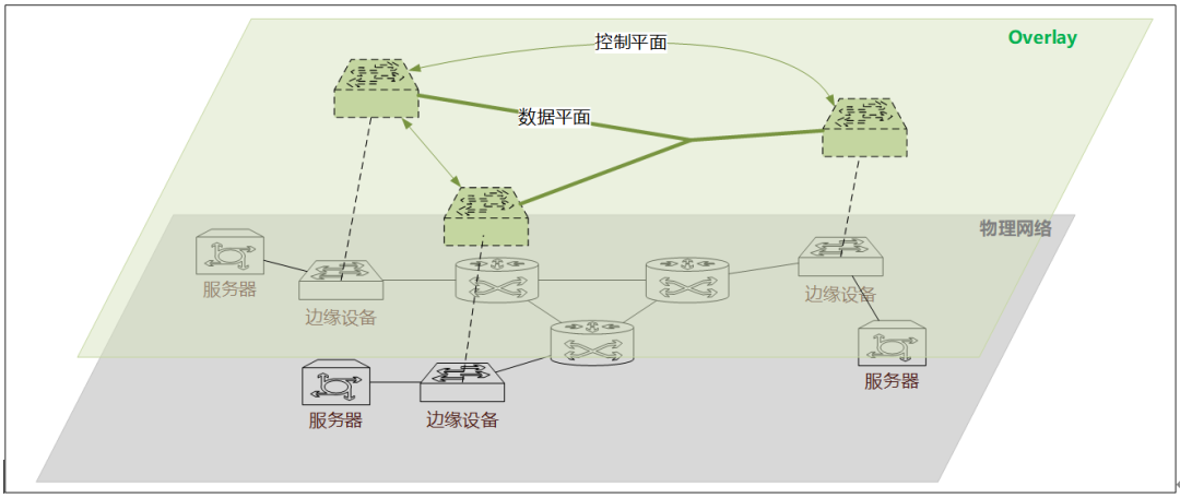
Overlay network technology refers to the virtualization technology mode superimposed on the traditional network architecture. That is to say, it relies on the premise of the traditional network architecture to realize the binding of the application to its virtual network and ignore the transmission mode and technology of the underlying physical network. To understand the overlay network architecture system, we first need to know its composition structure and elements. To understand these things, we must start with the difference between it and the traditional physical network architecture to understand in detail, as shown in Figure 1.1:

Figure 1.1 Overlay & traditional physical network architecture
As shown in Figure 1.1, the overlay network architecture is a layer of virtualized network based on the underlying physical network layer. That is to say, after partial adjustment of the traditional physical network, we have established a set of virtual transmission through logical abstraction. aisle. Then you may have a question: "How do we complete data transmission in this virtual network?"
Since the virtual network channel is established, the data packets transmitted by the application must be sent and transmitted based on the data packets that can be recognized by the virtual network, and must be transmitted in accordance with the channel control standards in the virtual network. However, we have to rely on the traditional physical network to realize the physical transmission of packets, which involves packet encapsulation and decapsulation, maintenance of logical channels, and logical and physical forwarding of data. This involves three core elements of the Overlay network:
- Edge device: The network device directly associated with the virtual network, the encapsulation/decapsulation site for data packets, and the physical node that forms the virtual network, such as the physical switch shown in the figure (must be a switch that supports the Overlay protocol).
- Control plane: The virtual entity in the framework is responsible for service discovery, address notification and mapping, and establishment and maintenance of virtual network channels in virtual network transmission, such as the control flow in the virtual layer in the figure.
- Data plane: The virtual entity in the framework is mainly responsible for the forwarding of data packets at the virtual layer, as shown in the data flow of the virtual layer.
1.2 Basic Rules of Overlay Network Transmission
The basic rules that traditional networks follow during data transmission are the seven-layer network model. That is to say, the data needs to go through the encapsulation process of the source and the unpacking process of the destination. When the packet is encapsulated, it is gradually encapsulated from the application layer information to the physical layer, and when unpacked, it is decomposed from the physical layer to the application layer. The basic addressing rules in the physical network environment rely on IP address information and MAC address information for routing and forwarding. So in the Overlay network, it will also follow this basic rule, but what is the difference?

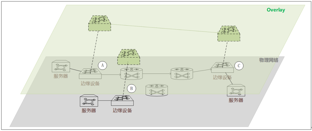
Figure 1. 2 Overlay & traditional physical network architecture
Taking VXLAN as an example, we combine Figure 1.2 to see its basic transmission rules. First, let's look at the three points of the edge device ABC of the Overlay network. These three points are the core devices that support the Overlay virtual network, which we call VTEP. When the data packet of the server passes through these edge devices, it will encapsulate the data packet twice, and encapsulate the address or identification information of the sender VTEP and the destination VTEP into the data packet, and then pass the VTEP control plane. The transmission is completed between the VTEPs, and then the data packets are decapsulated on the VTEP of the destination end, and finally sent to the destination server. You may have several questions here:
- If it is L3 transmission, isn't it superfluous to do so?
- If it is L2 transmission, how does the source VTEP know the VTEP information corresponding to the destination MAC and IP?
- Shouldn't the transmission between VTEPs also depend on the physical network? How is it passed from source to destination?
First of all, for the first question, if it is L3 transmission, it is really unnecessary to do so, so the source VTEP will judge whether it is a real L3 transmission. If so, it can discard the VTEP information and transmit it in the traditional way.
Next, for the second problem, the MAC information of all the devices under the jurisdiction of VTEP nodes will be retained on the VTEP, and the MAC address mapping information on other VTEPs will also be synchronized with each other, so once the destination address information in the data packet is obtained, the VTEP It can determine which VTEP jurisdiction the destination belongs to, and then forward it through the controller.
Finally, the transmission from one VTEP to another VTEP is completely based on the IP and MAC address information of the VTEP itself.
It can be seen that, whether it is L2 or L3 transmission, it involves table lookup and forwarding, and packet decapsulation and encapsulation operations. From the perspective of forwarding efficiency and execution performance, it can only be implemented on physical network devices (overlay edge devices), and traditional devices cannot support it and must be implemented through new hardware forms.
1.3 Technical Standards of Overlay Network
Currently, there are the following three technical routes under discussion in the Overlay technology field:
(1).VXLAN
VXLAN is a tunnel forwarding mode that encapsulates Ethernet packets on the UDP transport layer. In order to make VXLAN make full use of the balance of bearer network routing, VXLAN uses the HASH value of the original Ethernet data header (MAC, IP, Layer 4 port number, etc.) as the UDP number; uses 24 bits to identify the L2 network segment identifier, called It is VNI (VXLAN Network Identifier); network traffic such as unknown destination, broadcast, and multicast are encapsulated as multicast forwarding, and the physical network is required to support any-source multicast (ASM).
(2)NVGRE
NVGRE is a tunnel forwarding mode that uses the general routing encapsulation protocol to encapsulate packets. It uses the lower 24 bits of the GRE header as the Tenant Network Identifier (TNI). In order to provide flows that describe the granularity of bandwidth utilization, the transport network needs to use GRE headers, but this makes NVGRE incompatible with traditional load balancing, which is the biggest difference and biggest deficiency between NVGRE and VXLAN. NVGRE does not need to rely on flooding and IP multicast for learning, but broadcasts in a more flexible way, but this needs to rely on hardware. NVGRE supports reducing the packet MTU to reduce the internal virtual network packet size.
(3) STT
STT is a tunnel forwarding mode that uses TCP to encapsulate packets. It transforms the transmission mechanism of TCP and is a newly defined stateless mechanism. It redefines the meaning of each field of TCP and does not require three-way handshakes to establish a TCP connection, also known as It's called stateless TCP. Ethernet data is encapsulated in stateless TCP; 64 bits are used to identify L2 network segments; network load balancing is performed by taking the original Ethernet data header (MAC, IP, L4 port number, etc.) HASH value as the source port number of stateless TCP.
The three overlay technologies share a common technical model, which is to transform and encapsulate Ethernet packets and carry them to the logical tunnel level for forwarding. The technical characteristics of the differences lie in the differences in encapsulation and tunnel construction, while the bottom layer is IP forwarding. VXLAN and STT have lower requirements for traffic balancing on existing network devices, that is, the load balancing adaptability of load links is good, and general network devices can perform link aggregation or equal-cost routing traffic balancing for L2-L4 data content parameters. NVGRE, on the other hand, requires network devices to perceive the GRE extension header and perform hash calculation of the flow ID, which requires hardware support. The following is a description of the specific differences between the three overlay technology standards.
Table 1. 1 Comparison of Overlay Technical Standards
technical standard | way of support | Virtualization | encapsulated message | link load capacity |
VXLAN | UDP | 24bit VNI | 50Byte | L2-L4 HASH |
NVGRE | GRE | 24 bit VSI | 42Byte | N/A |
STT | Stateless TCP | 64 bit CID | 58~76Byte | L2-L4 HASH |
2. What problem does the overlay network solve?
Through the above analysis, we have a basic understanding of the basic architecture of the Overlay network and its basic transmission rules. So everyone must be very curious to know why this technology will appear in the big technical background of cloud computing? What specific problem can it solve in our specific historical period? In fact, there are three in summary, all of which are related to large-scale cloud data center application scenarios.
2.1 How the Overlay network solves the spatial limitation of L2
Although many traditional industries still use physical machines to deploy services, more and more computing tasks have been run on virtual machines and containers, and Kubernetes is now the de facto standard in the field of container orchestration. Due to routine update and maintenance and sudden failures, large-scale virtual machine and container migration in a cluster is relatively common.
When the host where the virtual machine is located goes down due to maintenance or other reasons, the current instance needs to be migrated to other hosts. In order to ensure that the service is not interrupted, we need to ensure that the IP address during the migration process remains unchanged, because the overlay is in the The network layer implements the L2 network, so as long as the network layer is reachable between multiple physical machines, a virtual local area network can be formed. After the virtual machine or container is migrated, it is still in the same layer 2 network, and there is no need to change the IP address. Thousands of machines A large cluster composed of physical machines makes it easier to schedule resources within the cluster. We can improve resource utilization, tolerate virtual machine errors, and improve node portability through virtual machine migration.

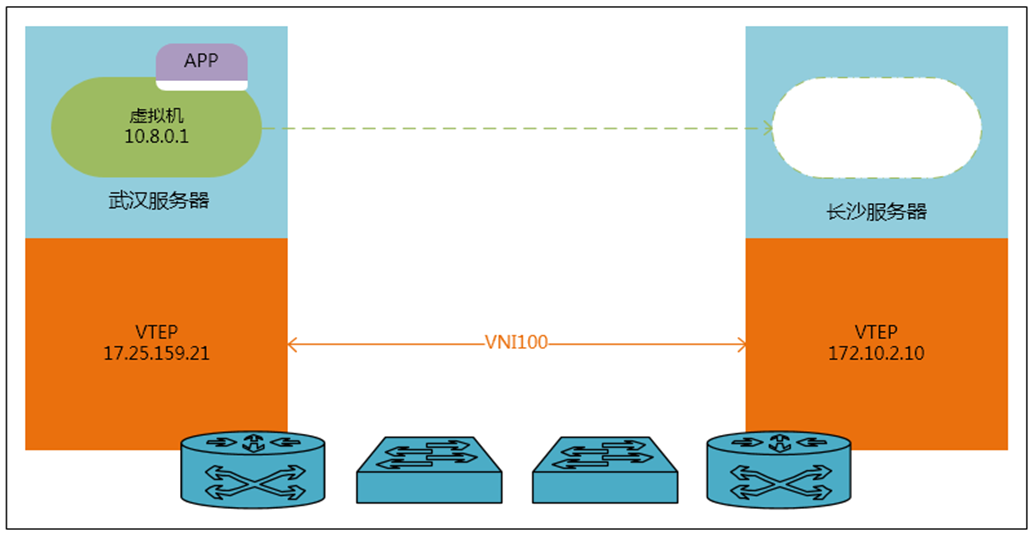
Figure 2. 1 Virtual machine migration under the overlay network architecture
As shown in the figure above, although the migrated virtual machine and other virtual machines are located in different data centers, since the two data centers can be connected through the IP protocol, the migrated virtual machine can still communicate with the original virtual machine through the overlay network. The virtual machines in the cluster form an L2 network. For the application, the address it publishes to the outside world does not change. For the virtual machine, it only knows that the remote host and the local host can form an L2 intercommunication local area network and can do VMotion. . However, the real data migration does experience the L3 transmission of traditional network equipment at the bottom layer. No matter what kind of transmission conversion is done by the bottom layer, as long as the upper layer protocol meets the migration conditions required by the application. In this way, the migration of L2 resources across regions is no longer an unsolvable problem. Without the support of this technology, I am afraid that even a bare fiber connection cannot solve this problem, after all, the distance of the fiber is limited.
2.2 How does the overlay network solve the limited network scale
The largest cluster officially supported by Kuberentes is 5,000 nodes. Usually, there are many containers on each node, so the resource scale of the entire cluster can reach tens of thousands or even hundreds of thousands. When a container sends an ARP request to the cluster, all containers in the cluster will receive the ARP request, which will bring extremely high network load. Traditional network technologies cannot tolerate network requests of this scale. In the overlay network built with VxLAN, the network will re-encapsulate the sent data into IP data packets, so that the network only needs to know the MAC addresses of different VTEPs, which can reduce the hundreds of thousands of data in the MAC address table entries to Thousands of ARP requests will only spread among the VTEPs in the cluster. After the remote VTEP unpacks the data, it will only broadcast locally and will not affect other VTEPs. There are higher requirements, but the pressure on core network equipment has been greatly reduced.
In addition, in the L2 network environment, the data flow needs to go through a clear network addressing to ensure the accurate arrival of the destination, so the MAC address table of the network device becomes the upper limit that determines the scale of the virtual machine in the cloud computing environment, and because the table The item is not 100% effective, which further reduces the number of available virtual machines, especially for low-cost access devices, because the table items are generally small in size, which limits the number of virtual machines in the entire cloud computing data center. After using the Overlay technology, the storage of the MAC address table is transferred to the VTEP device. Although the MAC and ARP specifications of core or gateway devices will also face challenges with the growth of virtual machines, for the capabilities of this layer of equipment, large specifications It is an unavoidable business support requirement. The way to reduce the pressure on access device specifications can be to separate gateway capabilities and use multiple gateways to share the termination and bearing of virtual machines.
2.3 How Overlay Networks Solve the Problem of Network Isolation
Large-scale data centers often provide external cloud computing services. The same physical cluster may be divided into multiple small blocks and assigned to different tenants. Because the data frames of the L2 network may be broadcast, for security reasons Network isolation is required between these different tenants to prevent traffic between tenants from influencing each other or even malicious attacks. The current mainstream network isolation technology is VLAN, which has two major limitations when deployed in a large-scale virtualized environment:
First of all, the number of VLANs in the standard definition is only 12 bit units, that is, the available number is about 4000, which is insignificant for public cloud or large-scale virtualized cloud computing applications. Secondly, the VLAN technology is currently a static configuration technology (only the 802.1Qbg technology of EVB/VEPA can dynamically deploy VLANs at the access layer, but it is also conventionally deployed on the port of the switch connected to the host, and the upstream port is still configured for all VLANs to pass through ), so that almost all VLANs in the entire data center network are allowed to pass through, causing broadcast data for unknown purposes to flood the entire network, consuming network switching capacity and bandwidth unchecked.
If the Overlay network technology is used, the above problems will be avoided. Take VXLAN as an example:
First, VxLAN uses 24-bit VNI to represent the number of virtual networks, which can represent a total of 16,777,216 virtual networks, far exceeding the 4,000 VLANs. This number is enough to meet the large-scale cluster requirements of today's cloud computing data centers. Secondly, VXLAN encapsulates data at the VTEP node during L2 transmission, so that more L2 broadcasts are converted into purposeful L3 transmission at the VTEP node, thereby avoiding uncontrolled network resource consumption. It not only satisfies the large-scale cluster network isolation problem, but also improves the network transmission security in this case.
3. Defects of Overlay Network Technology
Nothing can be perfect, and the same is true of Overlay technology.
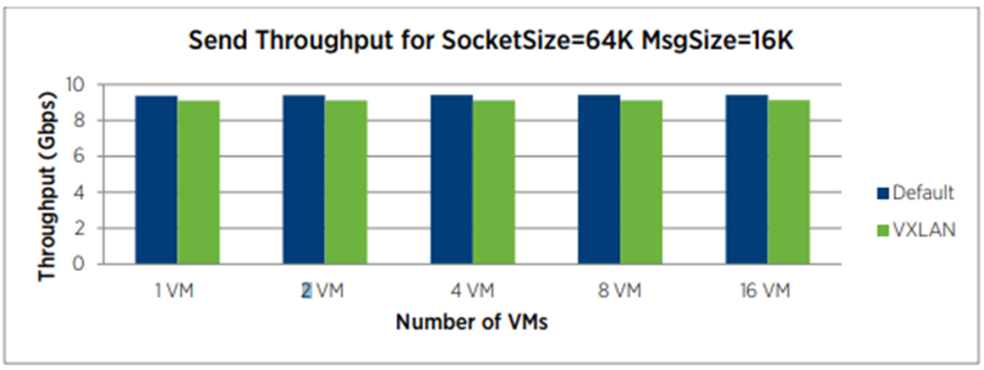
We can basically judge from the principle of Overlay technology. Compared with the traditional network, the performance of the Overlay network may be its problem, because no matter what kind of technical standard the Overlay network is, the data packets will be re-encapsulated and de-encapsulated again. This will undoubtedly bring performance delays to data transmission. Figure 3.1 shows the test results we intercepted:

Figure 3.1 VXLAN performance comparison
The above figure shows the comparison of the virtual machine transmission indicators under the default network configuration and the virtual machine under the VXLAN configuration in the VMware environment. Judging from the test results in the figure, in the VXLAN environment, no matter how the virtual machine changes, its The throughput of the transmission will be lower than the indicators under our normal network configuration.
In our enterprise IT environment, various types of applications exist, some of which have very high requirements for network performance, such as transactional database clusters in the financial industry, and the amount of data interaction between different cluster nodes varies from data size and transmission frequency All aspects are beyond ordinary applications, especially lock information, data cache blocks, and heartbeat information are the key factors that directly affect the operation of the database. Therefore, when we apply VXLAN, we also need to consider its shortcomings and choose the appropriate application scenario.
4. Summary and Outlook
Through the analysis in Sections 1 and 2 of this paper, we understand the basic framework, data transmission principles and basic technical standards of Overlay network technology, and also understand the root causes and inevitable trends of the popularity of Overlay network technology. Through the analysis in Section 3, we also understand some defects of the Overlay technology itself. Then I believe that in the process of application selection, everyone may have a more accurate grasp. However, with the development of technology and the rich application experience of enterprises, how to avoid its inevitable disadvantages and give full play to its natural advantages through improved methods or structural adjustments are issues that we need to discuss in the future, and what we hope to see. .